Rockwell Automation Publication 20B-IN026C-EN-P - October 2015 39
Chapter 3
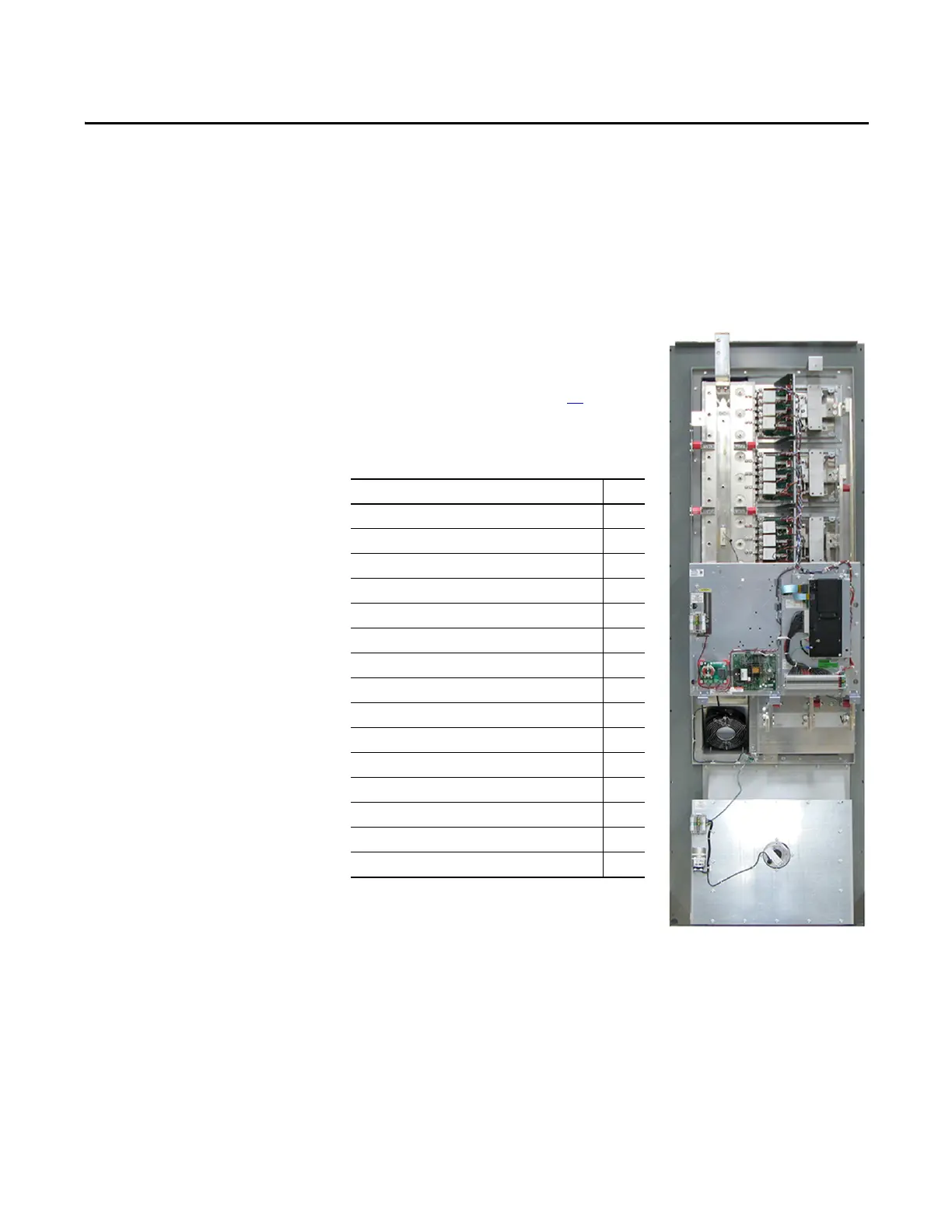
Inverter Assembly
Component Replacement Procedures
Overview
This section details components that are
replaceable on the Inverter assembly. See
Chapter 4 - Converter Assembly Component
Replacement Procedures on page 77
for
components replaceable on the Converter
assembly. The components addressed in this
section are as follows.
Inverter Assembly Component Page
Main Control Board (version 2.0) 40
T-Comm Board 42
Power Interface Board 45
Switch Mode Power Supply Board 47
24V Power Supply Board 49
DC Bus Filter Board 50
Bus Capacitors 51
Capacitor Bank Fan 53
Inverter Power Module (IGBT) 54
Gate Interface Board 60
Current Transducer 62
Heatsink Fan 64
Thermal Sensor 65
Balancing Resistor 67
Fan Transformer (IP20 version only) 76

 Loading...


