Rockwell Automation Publication 20B-IN026C-EN-P - October 2015 65
Inverter Assembly Component Replacement Procedures Chapter 3
Thermal Sensor
The Thermal Sensor system for the Inverter Assembly consists of:
• A connector to J8 on each of the three Gate Interface Boards. The J8
connectors are wired in series:
– J8 (V phase) has four wires: two wires that sense an over-temperature
condition, and two wires for temperature feedback.
– J8 (U phase) and J8 (W phase) have two wires that sense an
over-temperature condition only.
• A sensor (TSW3) is secured to the upper mounting bracket for the Main
Control Panel with a tripping point of 70 °C (158 °F).
• A connector to J6 on the Power Interface Board
.
See Chapter 1 - Component Diagrams and Torque Specifications on page 15 to
locate components in these instructions.
Remove Components
1. Read and follow the Safety Precautions on page 12 and Important Initial
Steps on page 13
.
2. Remove safety shields and enclosure covers as needed.
3. Cut the wire ties for the
wiring harness along the Gate
Interface Boards.
4. Note wire routing and
location of sensors.
5. For the Main Control Panel
thermal sensor, remove its
screw and nut on the Main
Control Panel and
disconnect the other end
from the wiring harness.
Note: This screw and nut are
small. Take care to not drop
or misplace.
6. Unplug the J8 connectors on each of the three Gate Interface Boards. See
page 60
for connector locations.
7. Unplug the other end of this wiring harness at the J6 connector on the
Power Interface Board. See page 42
for connector locations.
The inverter and converter assemblies are separate assemblies. Both
assemblies are included when you order AC input, but only the inverter
assembly is included when you order DC input.
If you purchased both units for AC input, then the thermal sensors must be
connected between the two units. See Thermal Sensor on page 88
for more
information.
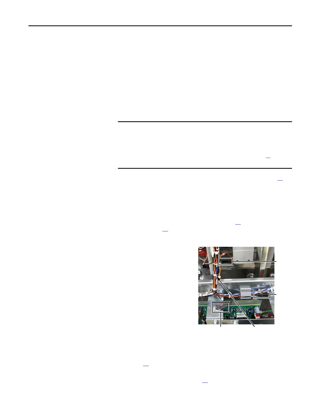
Wire Ties along
Gate Interface Boards
Heatsink
Thermal
Sensor &
Screw
Main Control Panel (MCP)
Thermal Sensor & Bracket
MCP
Thermal
Sensor
Wiring
Harness
End

 Loading...


