Rockwell Automation Publication 20B-IN026C-EN-P - October 2015 33
Basic Component Removal Procedures Chapter 2
Install Components
See the figures in the preceding Transitional Busbar Assembly (Inverter
Assembly) on page 29
section to identify any components discussed in this
section.
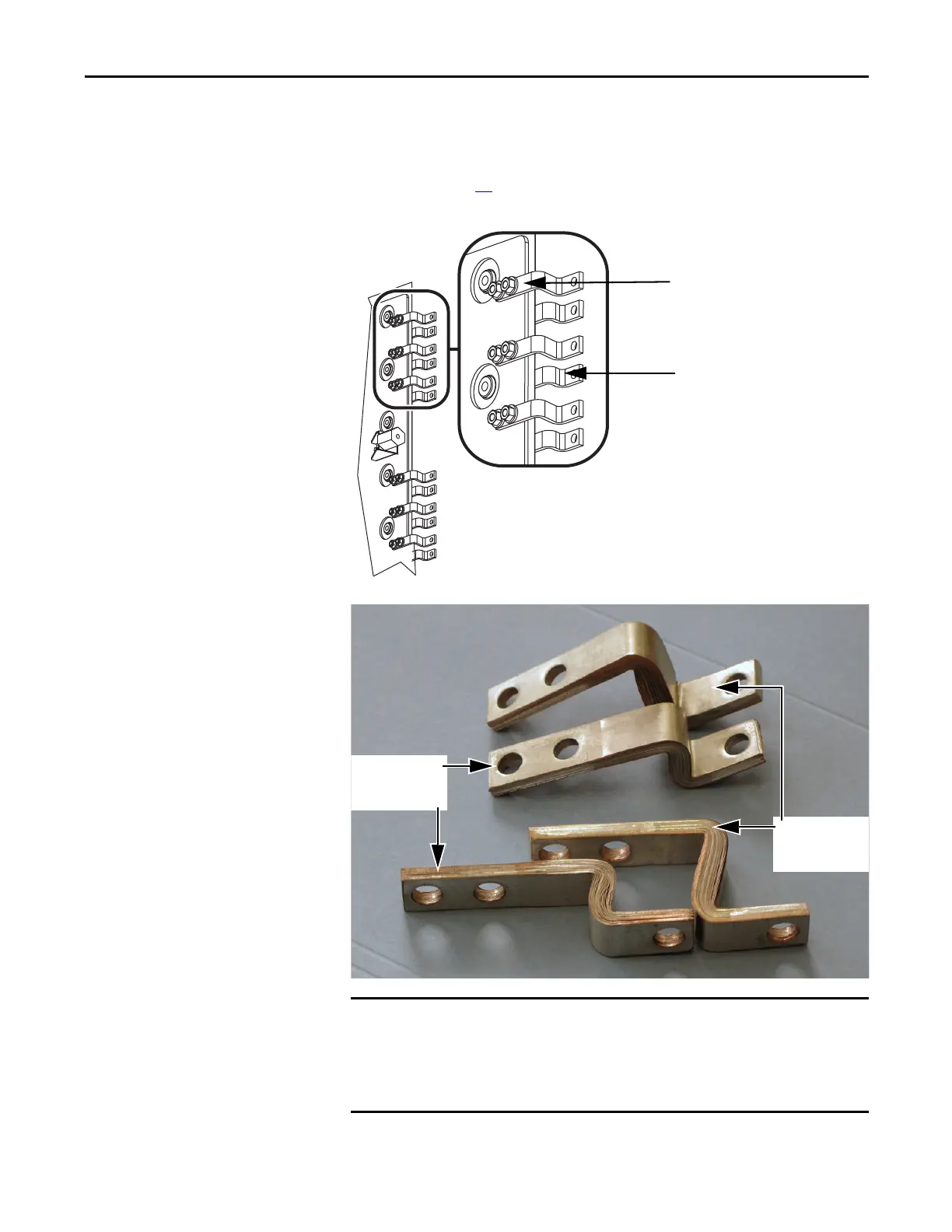
Each IGBT replacement kit includes three positive (DC+) and three negative
(DC-) Flexible Capacitor Busbars. The positive Flexible Capacitor Busbars are
shorter (see above) because they attach to the back side of the Transitional
Busbar assembly. For ease of installation, replace positive Flexible Capacitor
Busbars while the Transitional Busbar assembly is removed.
Negative (DC–) Flexible Capacitor Busbar
attached to top side of Transitional
Busbar Assembly (3).
Positive (DC+) Flexible Capacitor Busbar
attached to bottom side of Transitional
Busbar Assembly (3).
Negative (DC-)
Flexible Capacitor
Busbar (tall)
Positive (DC+)
Flexible Capacitor
Busbar (short)

 Loading...


