62 Rockwell Automation Publication 20B-IN026C-EN-P - October 2015
Chapter 3 Inverter Assembly Component Replacement Procedures
Current Transducer
See Chapter 1 - Component Diagrams and Torque Specifications on page 15 to
locate components in these instructions.
Remove Components
1. Read and follow the Safety Precautions on page 12 and Important Initial
Steps on page 13
.
2. Remove safety shields and enclosure covers as needed.
3. Locate the Current Transducer to be replaced.
4. Remove the Output Busbar at the Current Transducer. See Remove the
Output Busbar at the Current Transducer: on page 56
.
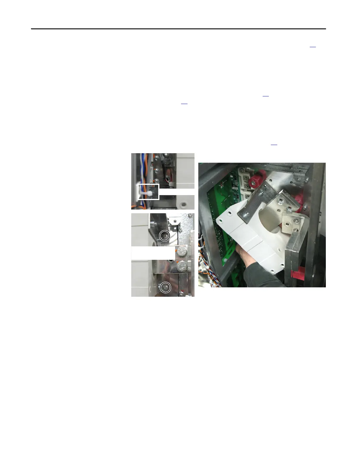
5. Remove the two torx screws that secure the Current Transducer assembly
(transducer and brackets) to the chassis.
6. Rotate the Current Transducer assembly counterclockwise and tip until
the Output Busbar clears the U, V, or W Busbar and spacer.
NOTE: Avoid any contact with the circuit board to the left of the
transducer being removed.
7. Move the busbar and transducer to an ESD-safe flat surface (where you can
continue the disassembly).
8. Separate the Output Busbar from the Current Transducer.
9. Separate the Current Transducer from the brackets.
10. Properly discard the Current Transducer.
Wire to Transducer
Transducer Assembly Torx
Screws (2)

 Loading...


