Rockwell Automation Publication 20B-IN026C-EN-P - October 2015 61
Inverter Assembly Component Replacement Procedures Chapter 3
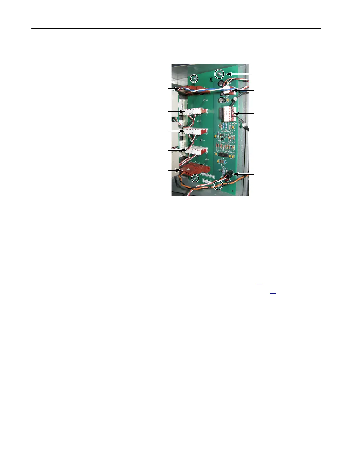
7. Remove the four mounting nuts.
8. Remove the Gate Interface Board; return or dispose of it properly.
Install Components
1. Install the new board.
2. Torque mounting nuts to 1.8 N•m (16 lb•in).
3. Reconnect wiring as detailed in the Table on the previous page.
4. If you removed the Main Control Panel and Stacking Panel to replace the
lower Gate Interface Board, replace the panels in this order:
a. Stacking Panel (Inverter Assembly) on page 26
.
b. Main Control Panel (Inverter Assembly) on page 24
.
5. Replace all safety shields and enclosure covers before applying power to the
drive.
Gate Interface Board
Mounting Nuts (4; 7 mm)
J1
J2
J3
J5
J4
J6
J8
J7

 Loading...


