54 Rockwell Automation Publication 20B-IN026C-EN-P - October 2015
Chapter 3 Inverter Assembly Component Replacement Procedures
Inverter Power Module
(IGBT)
This kit includes:
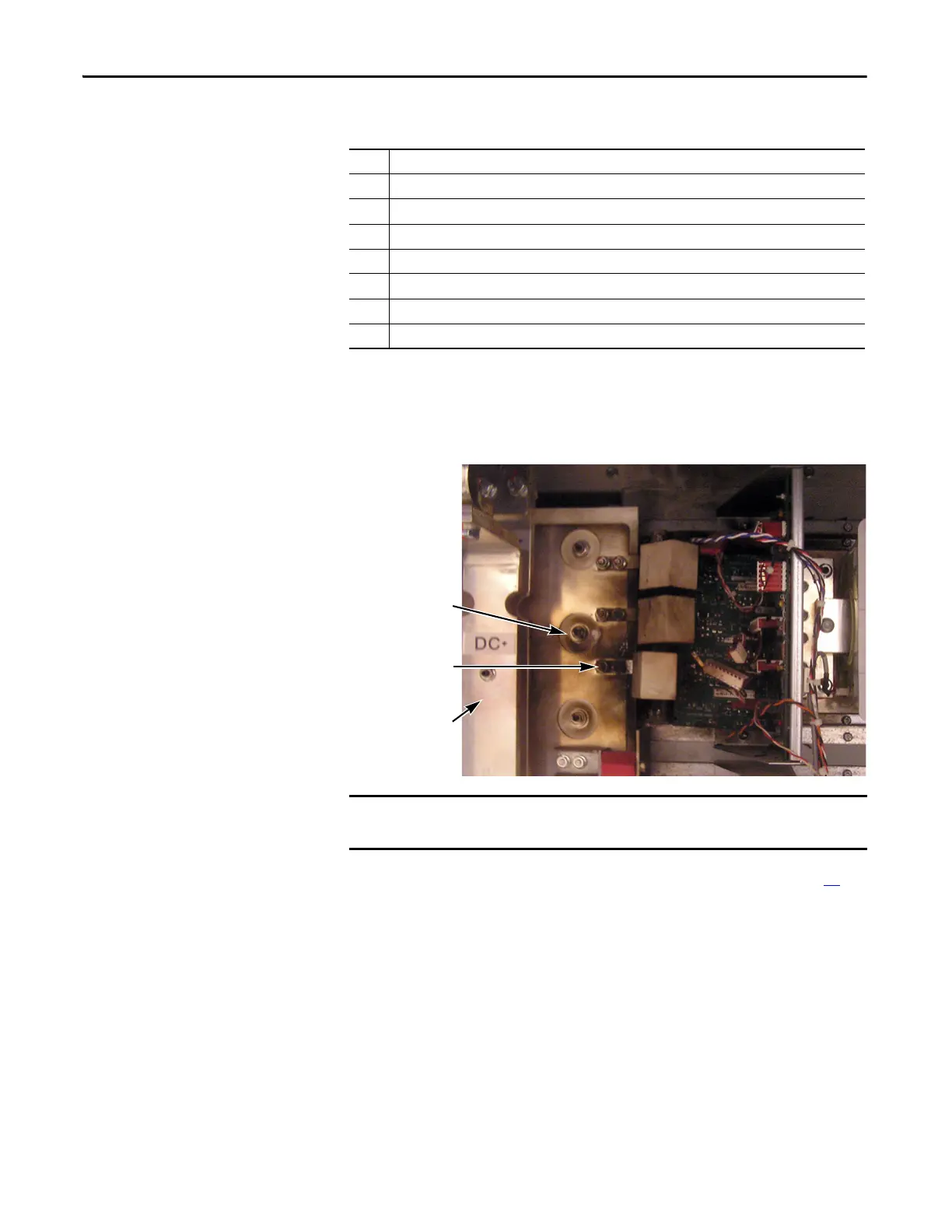
The photograph below is an example of an IGBT module failure. IGBT damage
may impact other components near or associated with IGBT operation,
including components that are not part of the Inverter Power Module (IGBT)
kit.
See Chapter 1 - Component Diagrams and Torque Specifications on page 15
to
locate components in these instructions.
Qty Component
1 IGBT module with circuit board
1 Gate Interface Board
1 Gate Interconnect Harness
3 Flexible Capacitor Busbar, Positive
3 Flexible Capacitor Busbar, Negative
1Tie Down Capacitor Mount
3 Snubber Capacitor
If any IGBT module is damaged, replace all IGBT modules and associated
components. Perform the following procedure for all IGBT modules.
Flexible Capacitor
Busbar, Negative
Transitional
Busbar Assembly
Bus Capacitor,
under Transitional
Busbar Assembly
Example of IGBT
Module Failure

 Loading...


