26 Rockwell Automation Publication 20B-IN026C-EN-P - October 2015
Chapter 2 Basic Component Removal Procedures
Stacking Panel
(Inverter Assembly)
See Chapter 1 - Component Diagrams and Torque Specifications on page 15 to
locate components in these instructions.
Remove Components
1. Read and follow the Safety Precautions on page 12 and Important Initial
Steps on page 13
.
2. Remove the Main Control panel. See Main Control Panel (Inverter
Assembly) on page 24
.
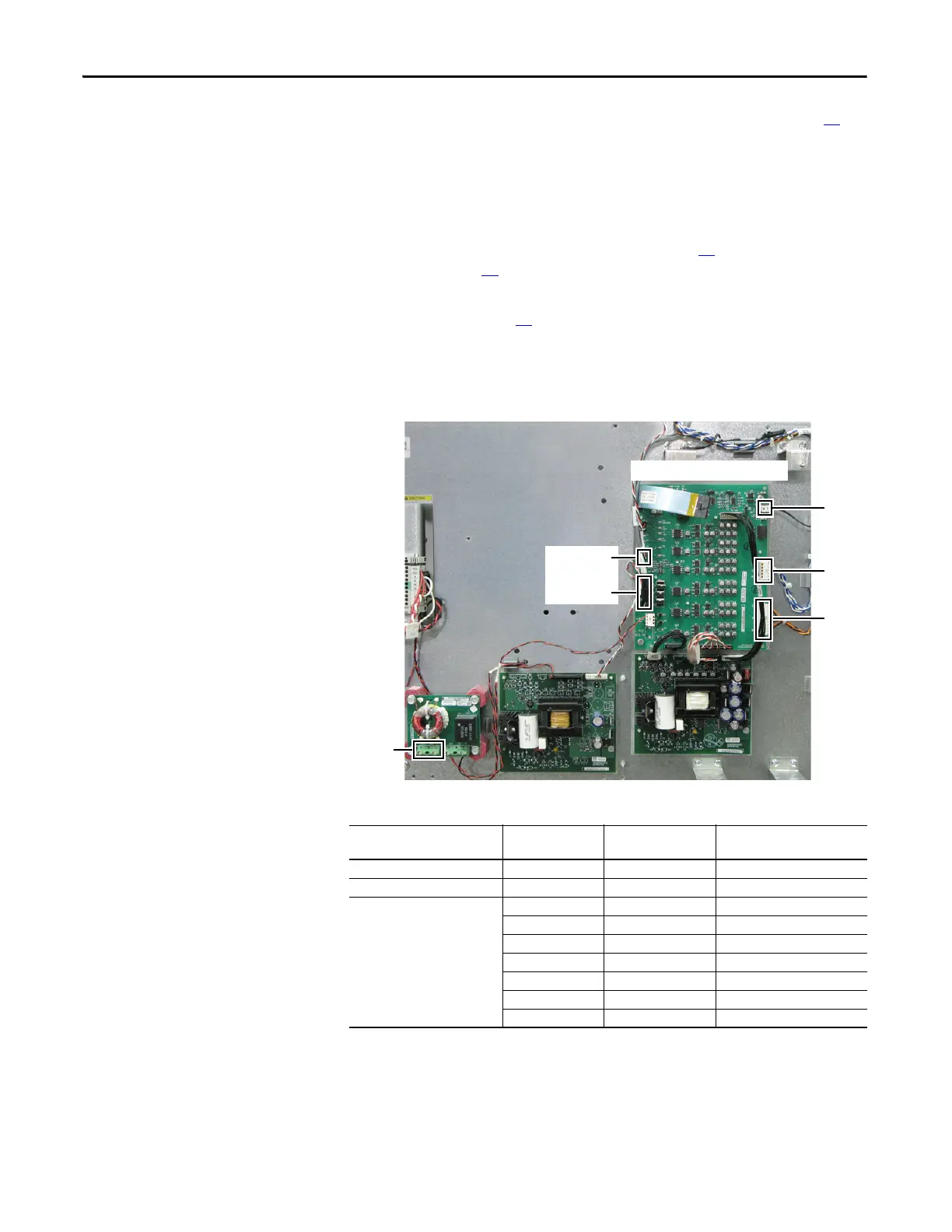
3. All wiring and terminals attached to the Stacking Panel are shown below.
Label any unidentified wiring and terminals before disconnecting.
4. Use your fingers or needle-nose pliers to squeeze the tabs of each of the
four spacers and remove the safety shield over the DC Bus Filter Board and
24V Power Supply Board.
Connected Component
Label on Wire
or Connector Label on Board Notes
DC Bus Filter Board TB2 To DC+/DC- Busbars
Thermal Sensor Wire To J6 of PIB
Power Interface Board (PIB) J6 J6 Thermal sensor connector
J8 J8 From U phase, J7
J16 U U Phase CT
J15 V V Phase CT
J14 W W Phase CT
J23 UP, VP, WP U, V, W positive gates
J18 UN, VN, WN U, V, W negative gates
J18
J23
J6
TB2
DC Bus Filter
Board
Switch Mode
Power Supply Board
Shown with Main Control Panel and Safety Shield Removed
J8
J14…J16
24V Power
Supply Board
Power Interface Board (PIB)

 Loading...


