EasyManuals Logo

Allen-Bradley powerflex 700 Installation Instructions

Allen-Bradley powerflex 700
96 pages
To Next Page IconTo Next Page
To Previous Page IconTo Previous Page
Page #27 background imageLoading...
Page #27 background image
Rockwell Automation Publication 20B-IN026C-EN-P - October 2015 27
Basic Component Removal Procedures Chapter 2
5. Carefully label and disconnect the red and black wires from TB2 on the
DC Bus Filter Board.
Do not disconnect the wires from TB1.
6. Disconnect the black Thermal Sensor Wire from J6.
Do not remove the sensor from the bracket.
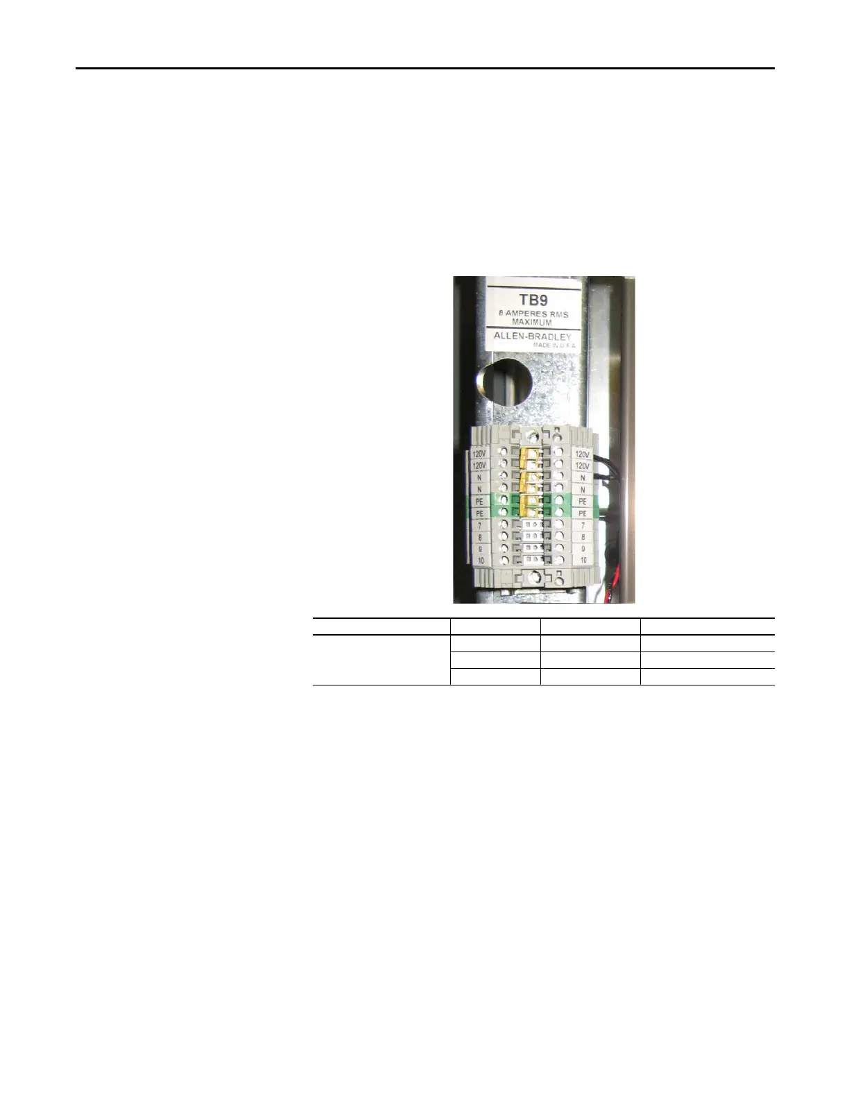
7. Carefully label and disconnect all wiring to TB9.
NOTE: TB9 shown with factory wiring only.
Connected Component Wire Color TB9 Terminal Notes
Capacitor Fan Harness Black 120V, right side Upper 120V slot
Black N, right side Upper N slot
Black PE, right side Lower PE slot

Table of Contents

Other manuals for Allen-Bradley powerflex 700

Questions and Answers:

Question and Answer IconNeed help?

Do you have a question about the Allen-Bradley powerflex 700 and is the answer not in the manual?

Allen-Bradley powerflex 700 Specifications

General IconGeneral
SeriesPowerFlex 700
CategoryAC Drive
Input Voltage200-240V AC, 380-480V AC, 500-600V AC
EnclosureType 1
Control MethodSensorless Vector
CommunicationEtherNet/IP, ControlNet, DeviceNet, PROFIBUS DP, Modbus

Related product manuals