38 Rockwell Automation Publication 20B-IN026C-EN-P - October 2015
Chapter 2 Basic Component Removal Procedures
Install Components
1. Reinstall the Busbars in reverse order of removal.
2. Reinstall the two set screw nuts that secure the DC– Busbar to the glastic
standoffs. Torque each set screw to 1.8 N•m (16 lb•in).
3. Reinstall the three bolts, washers, and nuts that secure the DC– Busbar to
the SCR Modules. Torque each bolt to 23.5 N•m (208 lb•in).
4. Reinstall the Snubber Resistor terminal wires or connectors to each
Snubber Board.
5. Hand tighten the Precharge Board J1 (black) terminal wire screw on the
DC– Busbar (lower left side).
6. Reinstall the two set screw nuts that secure each AC Busbar to the glastic
standoffs. Torque each set screw to 1.8 N•m (16 lb•in).
7. Reinstall the two bolts, washers, and nuts that secure each AC Busbar to
the SCR Modules. Torque each bolt to 23.5 N•m (208 lb•in).
8. Reinstall the terminal wires to each AC Busbar.
9. Torque each terminal wire screw to 5.6 N•m (50 lb•in).
10. Reinstall any AC input cables and connector bolts to the AC Bus Flags.
Torque each connector bolt to 23.5 N•m (208 lb•in).
11. Reinstall the two set screw nuts that secure each DC+ Busbar to the glastic
standoffs. Torque each set screw to 1.8 N•m (16 lb•in).
12. Reinstall the three bolts, washers, and nuts that secure the DC+ Busbar to
the SCR Modules. Torque the bolts to 23.5 N•m (208 lb•in).
13. Reinstall the wire from each of the Snubber Boards DC1 terminals to the
DC+ Busbar. Torque the bolts to 3 N•m (26 lb•in).
14. Replace all safety shields and enclosure covers before applying power to the
drive.
To Terminal From Wire Color
Snubber Boards (R) J1 Snubber Resistor (R) Black
J2 Snubber Resistor (R) Blue
DC1 Precharge Board J1 Red Wire Red
DC+ Busbar Black
Snubber Boards (S) J1 Snubber Resistor (S) Black
J2 Snubber Resistor (S) Blue
DC1 DC+ Busbar Black
Snubber Boards (T) J1 Snubber Resistor (T) Black
J2 Snubber Resistor (T) Blue
DC1 DC+ Busbar Black
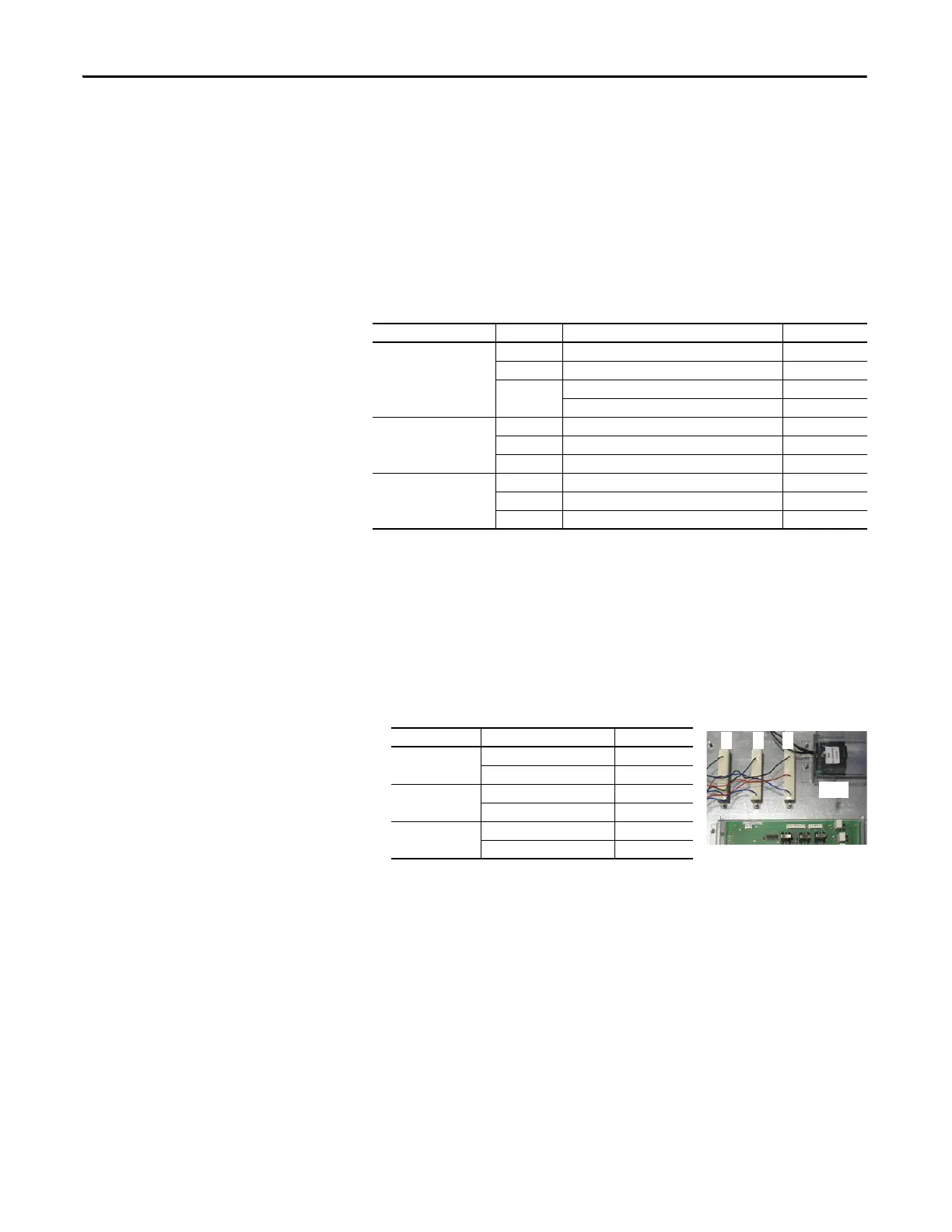
To From Wire Color
AC Busbar (R) Snubber Resistor (R) Red
MOV Black
AC Busbar (S) Snubber Resistor (S) Red
MOV Black
AC Busbar (T) Snubber Resistor (T) Red
MOV Black
MOV
R
Snubber Resistors (3)
S T
Precharge Board

 Loading...


