84 Rockwell Automation Publication 20B-IN026C-EN-P - October 2015
Chapter 4 Converter Assembly Component Replacement Procedures
Snubber Resistors
See Chapter 1 - Component Diagrams and Torque Specifications on page 15 to
locate components in these instructions.
Remove Components
1. Read and follow the Safety Precautions on page 12 and Important Initial
Steps on page 13
.
2. Remove safety shields and enclosure covers as needed.
3. Locate the Snubber Resistor(s) to be replaced.
4. Carefully label and disconnect all wires for the Snubber Resistor(s). See
AC Busbars on page 36
to locate the AC Busbar screws for the red wire(s).
5. Remove the Snubber Resistor(s) mounting screws.
6. Remove the Snubber Resistor(s) and dispose of properly.
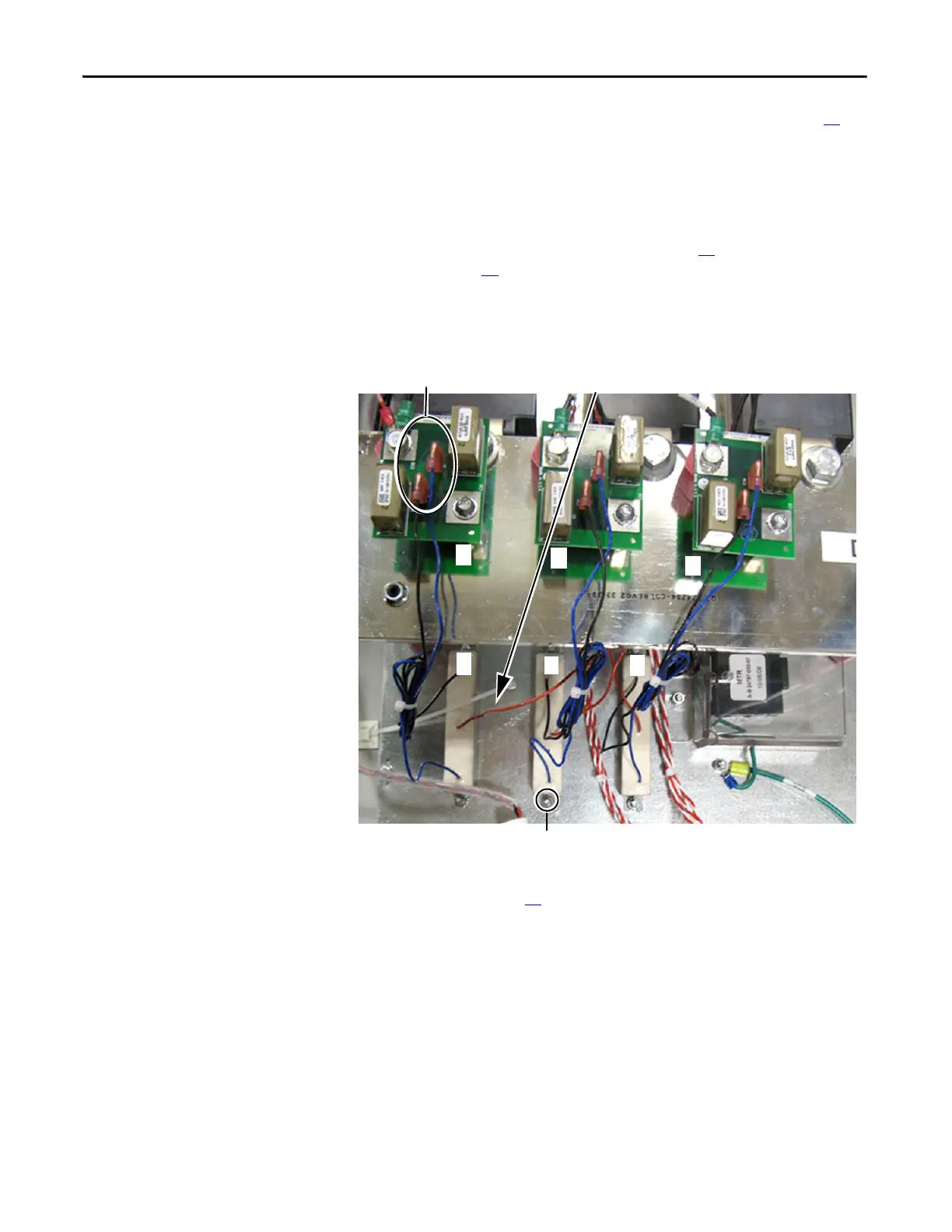
Snubber Resistors (3) and Mounting Screws (2 each)
Snubber Board
J1 and J2 Connectors
Red Wire is connected to its Respective AC Busbar: R, S,
or T
R
S
T
R
S
T

 Loading...


