36 Rockwell Automation Publication 20B-IN026C-EN-P - October 2015
Chapter 2 Basic Component Removal Procedures
5. Remove the three bolts, washers, and nuts that secure the Busbar to each
SCR Module, and save.
6. Remove the two set screw nuts that secure the busbar to the glastic
standoffs and save.
7. Remove the DC+ Busbar.
8. Label any AC input cables according to which Bus Flags (R, S, or T) they
are connected.
9. Disconnect any AC input cables from the AC Bus Flags and save the
connector bolts.
10. Label the wires and remove the screw from each AC Busbar that secures
the red wires and the black wires, and save.
• Red Wire: from the R, S, or T Snubber Resistor to the R, S, or T
AC Busbar
• Black Wire: from the MOV
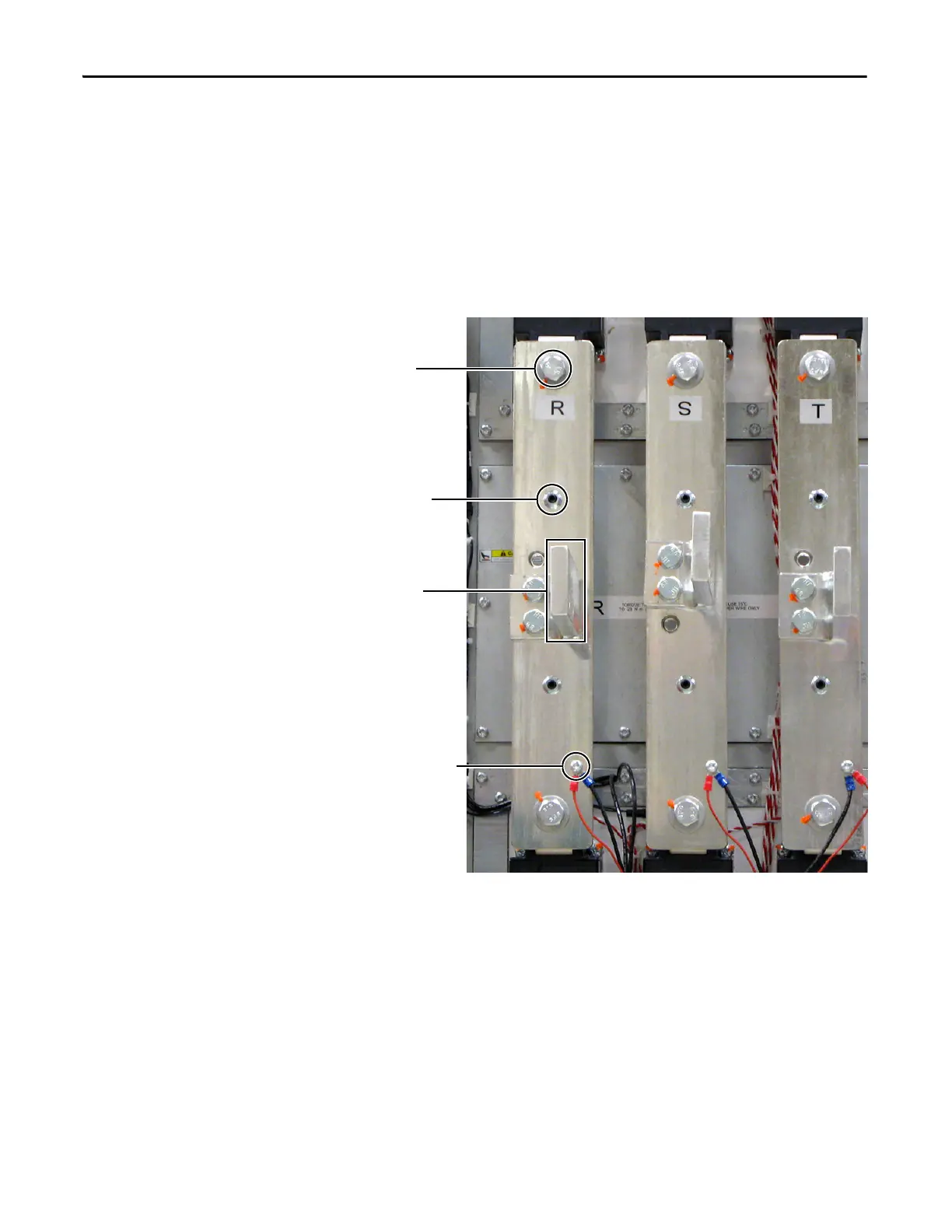
Shown with AC Input Cables and Connecting Bolts Removed
AC Busbar
Mounting Bolt (2
per Busbar)
Set Screw Nut for
Glastic Standoff (2
per Busbar)
AC Bus Flags
(1 per Busbar)
MOV Wires (black) and
Corresponding Snubber
Resistor Wires (red).
(1 screw per Busbar)

 Loading...


