Rockwell Automation Publication 20B-IN026C-EN-P - October 2015 35
Basic Component Removal Procedures Chapter 2
16. Reinstall the DC Choke output cables.
17. Reinstall any customer wiring to the Transitional Busbar assembly.
18. Reinstall the Stacking Panel as instructed on page 28
.
19. Reinstall the Main Control Panel as instructed on page 25
.
20. Verify all wiring to the two panels and the Transitional Busbar assembly
has been reconnected.
21. Replace all safety shields and enclosure covers before applying power to the
drive.
Busbar Assembly
(Converter Assembly)
See Chapter 1 - Component Diagrams and Torque Specifications on page 15 to
locate components in these instructions.
Remove Components
1. Read and follow the Safety Precautions on page 12 and Important Initial
Steps on page 13
.
2. Remove safety shields and enclosure covers as needed.
3. Remove the DC Choke cables from the DC+/DC- Busbars.
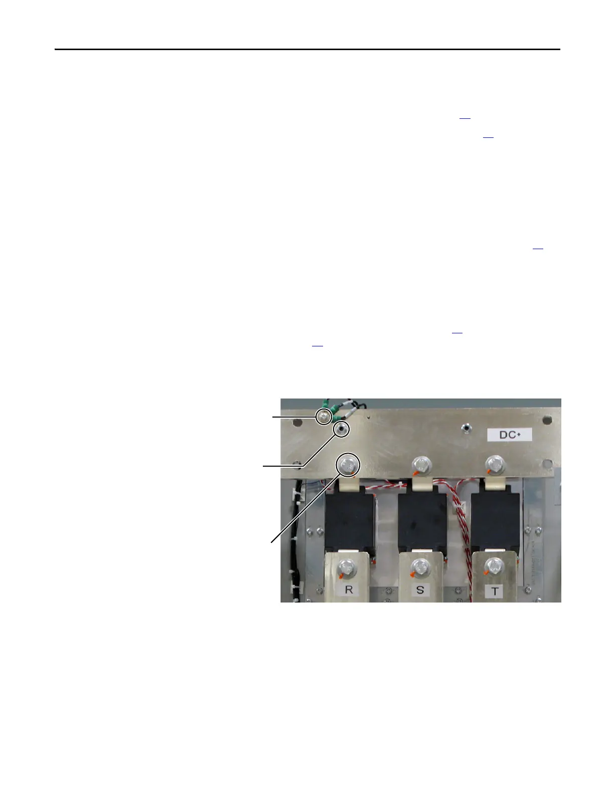
4. Label the wires and remove the screw that secures the three wires from the
Snubber Board DC1 screw terminal to the DC+ Busbar, and save.
Wires from
Snubber Board
Screw Terminal
(DC1)
Set Screw
Nuts (2) for
Glastic Standoffs
Bolt, Washer
and Nut
(3 each)

 Loading...


