Rockwell Automation Publication 20B-IN026C-EN-P - October 2015 57
Inverter Assembly Component Replacement Procedures Chapter 3
Install Components
1. Carefully examine the Transitional Busbar Assembly and Bus Capacitors
for damage.
When replacing any IGBT module, we recommend that you replace all
Bus Capacitors. If needed, see Bus Capacitors on page 51
to replace
damaged Bus Capacitors.
2. Install the IGBT module.
a. Use isopropyl alcohol to thoroughly clean the surface of the Heatsink.
b. Verify that the mounting surface of the new IGBT module is clean. If
not, clean the mounting surface with isopropyl alcohol.
c. Use a 3- or 4-inch paint roller or putty knife to apply a thin even coating
of the supplied thermal grease to the mounting surface of the IGBT
module.
In the next step, take care to not disturb any of the thermal grease on the
IGBT module.
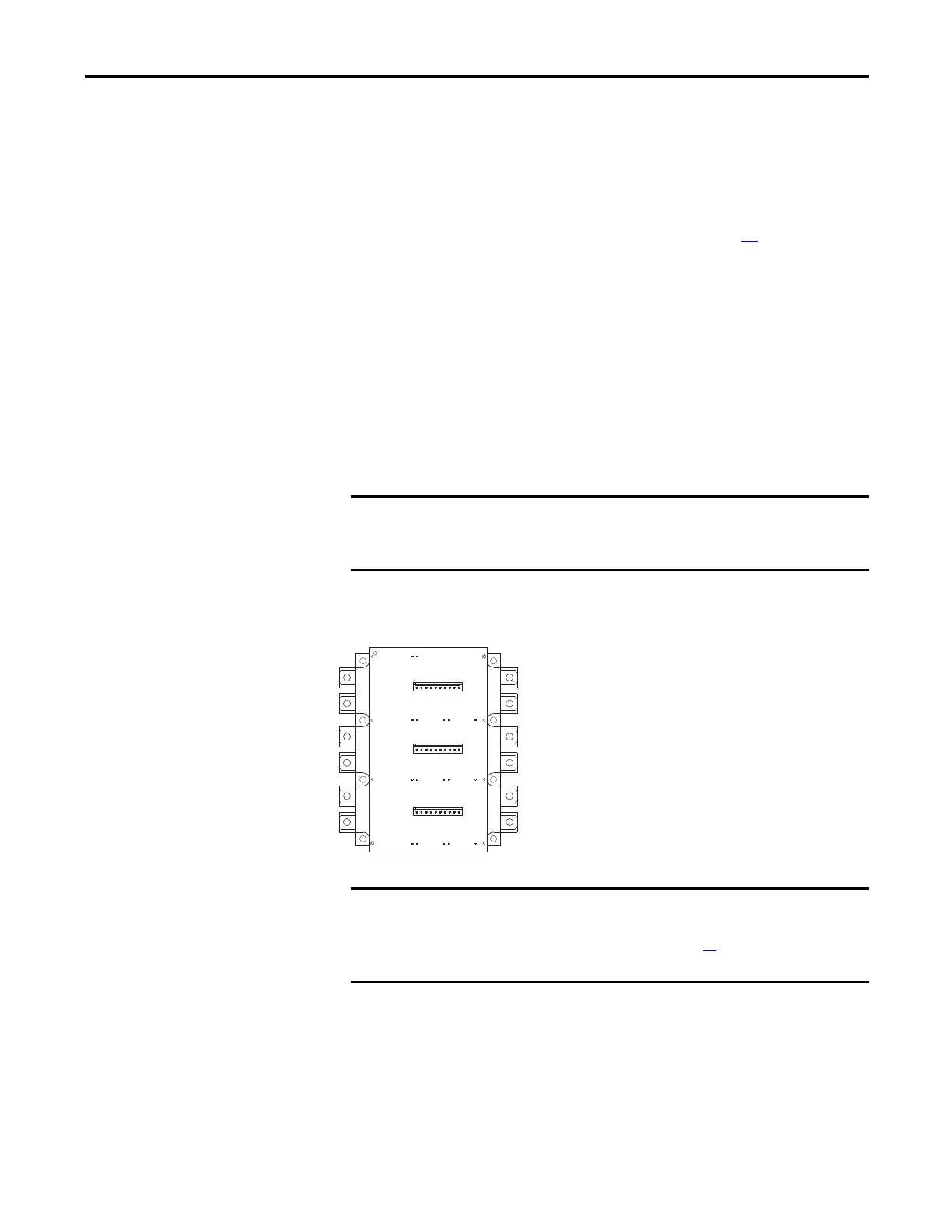
d. Place the IGBT on the chassis with the serial number label at the top.
Install with supplied screws using this torque sequence:
If the Transitional Busbar Assembly was not removed, take care to not
damage the Flexible Capacitor Busbars fitting over and under the
Transitional Busbar Assembly.
➑
➋
➍
➏
➎
➌
➊
➐
IGBT Torque Sequence
First Sequence: 0.7 N•m (6.0 lb•in)
Second Sequence: 1.5 N•m (14 lb•in)
Final Sequence: 5.6 N•m (50 lb•in)
The three positive (+) Flexible Capacitor Busbars supplied with the kit must
be installed on the back side of the Transitional Busbar Assembly before
they can be installed on the IGBT. See page 33
for how to install these
busbars on the Transitional Busbar Assembly.

 Loading...


