58 Rockwell Automation Publication 20B-IN026C-EN-P - October 2015
Chapter 3 Inverter Assembly Component Replacement Procedures
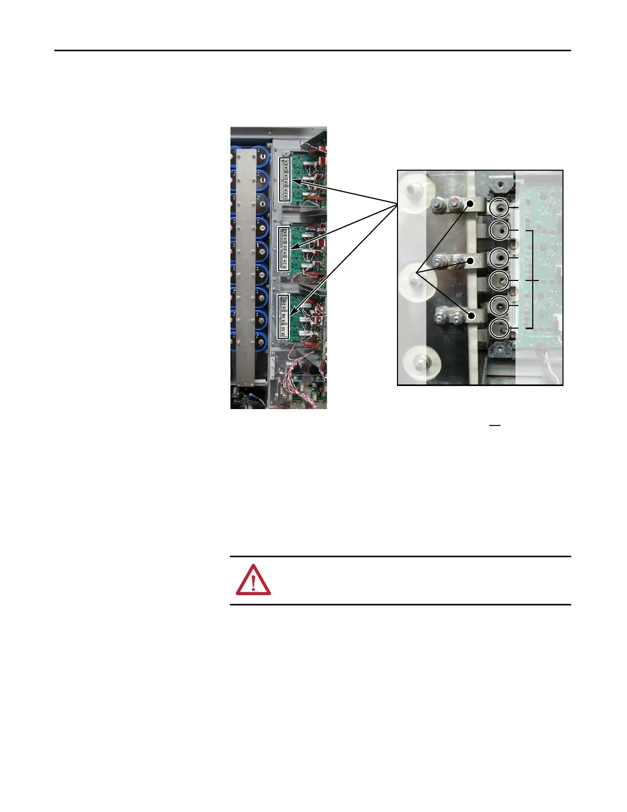
3. If needed, install the three supplied positive (DC+) Flexible Capacitor
Busbars on the back side of the Transitional Busbar Assembly.
The positive (DC+) Flexible Capacitor Busbars have a shorter angle.
4. Reinstall the Transitional Busbar as instructed on page 33
.
5. Install the three supplied negative (DC-) Flexible Capacitor Busbars in
positions 1, 3, and 5 on the IGBT module.
The negative (DC-) Flexible Capacitor Busbars have a higher angle.
6. Install the Tie Down Capacitor Mount:
a. Insert the short ends of the six threaded studs with nuts through the
Flexible Capacitor Busbars and into the left side of the IGBT module.
Torque to 5.6 N•m (50 lb•in).
b. Install the Tie Down Capacitor Mount with the two screws previously
removed from the top and bottom of the Capacitor Mount. Torque to
2.9 N•m (26 lb•in).
WARNING: Correct torque is critical to ensure correct operation of the
drive. Improper torquing could cause premature failure when
attempting to operate the drive.
Positive (DC+) Flexible Capacitor Busbars
Shown with Transitional Busbar and
all Flexible Capacitor Busbars installed
for illustration purposes only
1
2
3
4
5
6
Negative (DC-) Flexible Capacitor Busbars

 Loading...


