Rockwell Automation Publication 20B-IN026C-EN-P - October 2015 77
Chapter 4
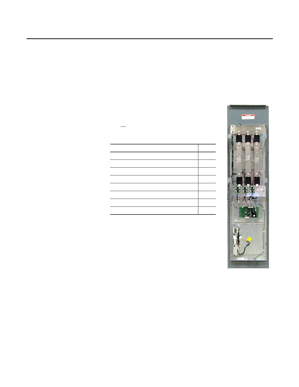
Converter Assembly
Component Replacement Procedures
Overview
This section details components that are replaceable
on the converter assembly. See Chapter 3 - Inverter
Assembly Component Replacement Procedures on
page 39
for components replaceable on the inverter
assembly. The components addressed in this section
are as follows.
Converter Assembly Component Page
DC Link Choke 78
MOV Surge Suppressor 79
Converter Power Modules (SCR) 80
Precharge Board 83
Snubber Resistors 84
Snubber Boards 86
Thermal Sensor 88
Heatsink Fan Assembly 90

 Loading...


