24 Rockwell Automation Publication 20B-IN026C-EN-P - October 2015
Chapter 2 Basic Component Removal Procedures
Main Control Panel
(Inverter Assembly)
See Chapter 1 - Component Diagrams and Torque Specifications on page 15 to
locate components in these instructions.
Remove Components
1. Read and follow the Safety Precautions on page 12 and Important Initial
Steps on page 13
.
2. Remove safety shields and enclosure covers as needed.
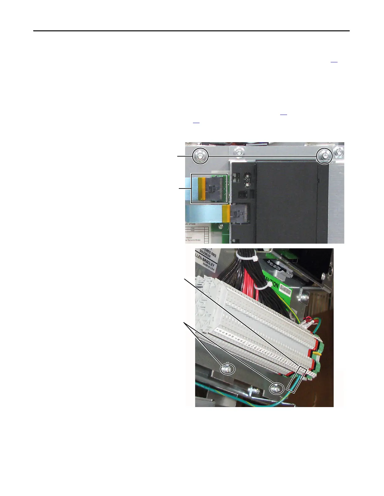
3. Remove the ribbon cable going from the Main Control Board (J2) to the
Power Interface Board (J1).
4. Disconnect the incoming ground wire to TB11.
5. Remove the two mounting nuts at the top of the Main Control Board.
Ribbon Cable from
Main Control Board to
Power Interface Board
(top cable)
Mounting Nuts (2)
Ground Wire to TB11
Mounting Screws (2)
below TB11

 Loading...


