Rockwell Automation Publication 20B-IN026C-EN-P - October 2015 23
Chapter 2
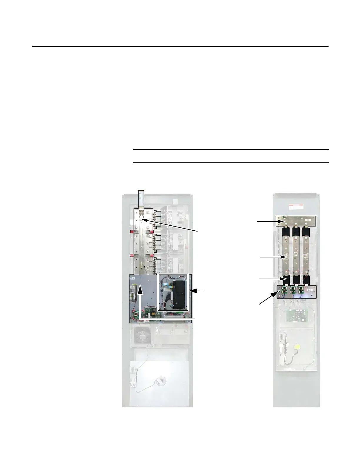
Basic Component Removal Procedures
Component removal procedures detailed in this chapter are located on the
Inverter and Converter assemblies highlighted below. Components removed in
this chapter are to access the Bus Capacitors in the Inverter assembly and the
SCR Modules in the Converter assembly.
Photos are for illustration purposes only. Actual components may vary.
Transitional Busbar
Assembly
Stacking Panel
Assembly
Inverter Assembly Converter Assembly
DC+ Busbar
AC Busbars (3)
DC- Busbar
SCR Modules (6)
Main Control Panel

 Loading...


