Rockwell Automation Publication 20B-IN026C-EN-P - October 2015 45
Inverter Assembly Component Replacement Procedures Chapter 3
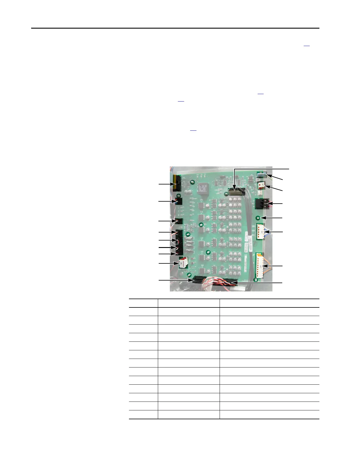
Power Interface Board
See Chapter 1 - Component Diagrams and Torque Specifications on page 15 to
locate components in these instructions.
Remove Components
1. Read and follow the Safety Precautions on page 12 and Important Initial
Steps on page 13
.
2. Remove safety shields and enclosure covers as needed.
3. Remove the Main Control Panel. See Main Control Panel (Inverter
Assembly) on page 24
.
4. Remove wiring to the Power Interface Board.
5. Remove wiring from the Power Interface Board to the Switch Mode Power
Supply Board.
Connector Wire Color(s) Connects To:
J1 Ribbon J2 on Main Control Board (ribbon cable)
J2 Black J1 on Switch Mode Power Supply Board
J6 Black Monitor wire to thermal sensors
J8 Red/White/Black J7-U on U Phase Gate Interface Board
J9 Red/White/Black J1 on 24V Power Supply Board
J10 Red/Black/White/Blue J3 on Precharge Board
J12 Red/White J3 on Switch Mode Power Supply Board
J13 Black J2 on Switch Mode Power Supply Board
J14 Red/White/Black U Phase Current Transducer
J15 Red/White/Black V Phase Current Transducer
J16 Red/White/Black W Phase Current Transducer
J18 Blue/White U, V, W negative (–) gates (lower phase)
J23 Orange/Black U, V, W positive (+) gates (upper phase)
J1
J10
J8
J9
J16
J15
J14
J24
J13
J23
J18
TB2
J6
TB1
J2
Spacers (9)
J12

 Loading...


