46 Rockwell Automation Publication 20B-IN026C-EN-P - October 2015
Chapter 3 Inverter Assembly Component Replacement Procedures
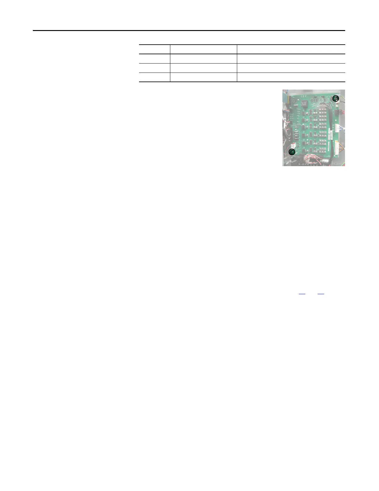
6. Remove the two mounting torx screws located
on the board as shown at right.
7. Use your fingers or needle-nose pliers to
squeeze the tabs of each of the nine spacers
(see previous page for their locations), and
separate the Power Interface Board from the
mounting plate.
8. Remove the Power Interface Board; return or
dispose of it properly.
Install Components
1. Install the new Power Interface Board.
Tighten board screws to 1.8 N•m (16 lb•in).
2. Reconnect all wiring as detailed in the Table on the previous page.
3. Reconnect the Main Control Board wires to TB1 and TB2 on the Power
Interface Board.
4. Tighten sheet metal screws to 3.2 N•m (28 lb•in).
5. Reconnect the ribbon cable going from the Power Interface Board (J1) to
the Main Control Board (J2).
6. Reinstall the Main Control Board as instructed on page 24
and 25.
7. Replace all safety shields and enclosure covers before applying power to the
drive.
J24 Red/Black TB1 on DC Bus Filter Board
TB1 Green/Yellow PE on TB11
TB2 Red #33, #34, and #35 on TB11
Connector Wire Color(s) Connects To:

 Loading...


