Rockwell Automation Publication 20B-IN026C-EN-P - October 2015 47
Inverter Assembly Component Replacement Procedures Chapter 3
Switch Mode Power Supply
Board
See Chapter 1 - Component Diagrams and Torque Specifications on page 15 to
locate components in these instructions.
Remove Components
1. Read and follow the Safety Precautions on page 12 and Important Initial
Steps on page 13
.
2. Remove safety shields and enclosure covers as needed.
3. Remove the Main Control Panel. See Main Control Panel (Inverter
Assembly) on page 24
.
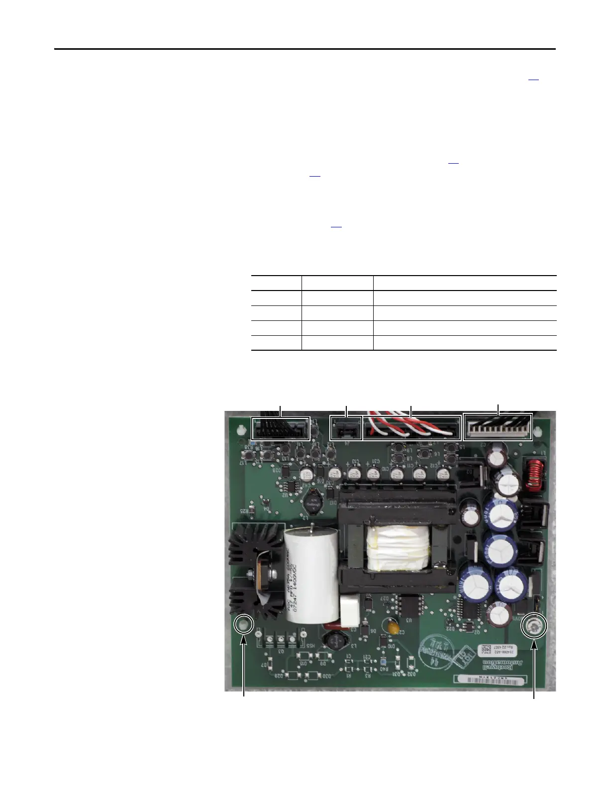
4. Carefully label and disconnect all wiring from the Switch Mode Power
Supply Board.
5. Remove the Switch Mode Power Supply Board mounting torx screw
located at the lower right corner of the board.
Connector Wire Color(s) Connects To:
J1 Black J2 on Power Interface Board
J2 Black J13 on Power Interface Board
J3 Red/White J12 on Power Interface Board
J4 Open
Torx Screw
Spacers (3)
J2 J4 J3
J1

 Loading...


