60 Rockwell Automation Publication 20B-IN026C-EN-P - October 2015
Chapter 3 Inverter Assembly Component Replacement Procedures
Gate Interface Board
See Chapter 1 - Component Diagrams and Torque Specifications on page 15 to
locate components in these instructions.
Remove Components
1. Read and follow the Safety Precautions on page 12 and Important Initial
Steps on page 13
.
2. Remove safety shields and enclosure covers as needed.
3. Locate the Gate Interface Board to be replaced.
4. If you are replacing the lower Gate Interface Board, it may be easier if you
remove the Main Control Panel and Stacking Panel. If you need to remove
the panels, remove them in this order:
a. Main Control Panel (Inverter Assembly) on page 24
.
b. Stacking Panel (Inverter Assembly) on page 26
.
5. Remove the safety cover over the Gate Interface Board.
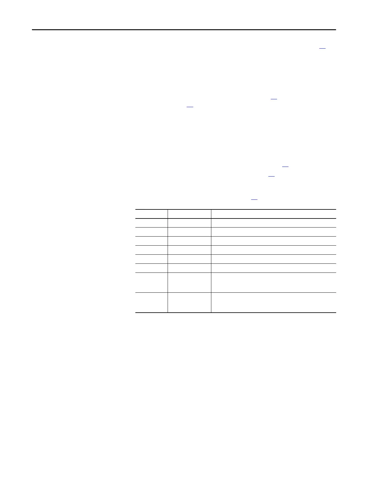
6. Label and disconnect all wires (see page 61
).
Connector Wire Color(s) Connects To:
J1 Red/White/Black J1 on IGBT Module
J2 Red/White/Black J2 on IGBT Module
J3 Red/White/Black J3 on IGBT Module
J4 Orange/Black J23 on Power Interface Board
J5 Blue/White J18 on Power Interface Board
J6 Red/White J4 on IGBT Module
J7 Red/White/Black J7-W to J7-V (Gate Interface Boards W and V)
J7-V to J7-U (Gate Interface Boards V and U)
J7-U to J8 on Power Interface Board
J8 Black J8-W to J8-V (Gate Interface Boards W and V)
J8-V to J8-U (Gate Interface Boards V and U)
J8-U to J6 on Power Interface Board

 Loading...


