Rockwell Automation Publication 20B-IN026C-EN-P - October 2015 51
Inverter Assembly Component Replacement Procedures Chapter 3
Bus Capacitors
See Chapter 1 - Component Diagrams and Torque Specifications on page 15 to
locate components in these instructions.
Remove Components
1. Read and follow the Safety Precautions on page 12 and Important Initial
Steps on page 13
.
2. Remove safety shields and enclosure covers as needed.
3. Remove the Main Control Panel. See Main Control Panel (Inverter
Assembly) on page 24
.
4. Remove the Stacking Panel. See Stacking Panel (Inverter Assembly) on
page 26
.
5. Remove the Transitional Busbar assembly. See Transitional Busbar
Assembly (Inverter Assembly) on page 29
.
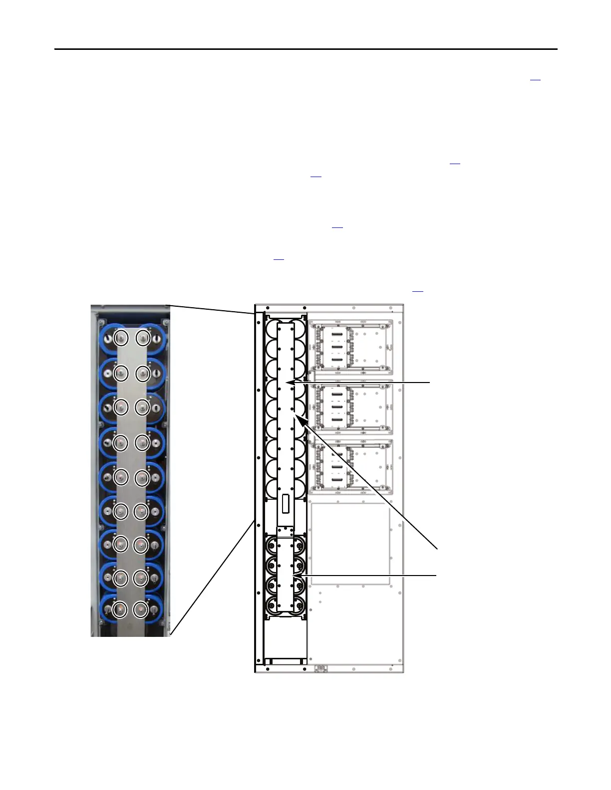
6. Label and remove all wires and connectors from the Bus Capacitor Busbar.
7. Remove nuts and washers (26) fastening the Bus Capacitor Busbar to the
Bus Capacitors.
Bus Capacitor Busbar
Transitional Busbar
Assembly Removed
Bus Capacitor Busbar
Nuts and Washers (26)
Upper (18)
Lower (8)
Upper Bus Capacitor Busbar Shown with 18
mounting nuts and washers.

 Loading...


