52 Rockwell Automation Publication 20B-IN026C-EN-P - October 2015
Chapter 3 Inverter Assembly Component Replacement Procedures
8. The set screws may come out with the nuts. Save all nuts and set screws.
9. Remove the Bus Capacitor Busbar.
10. Remove the Capacitors by pulling them out.
Install Components
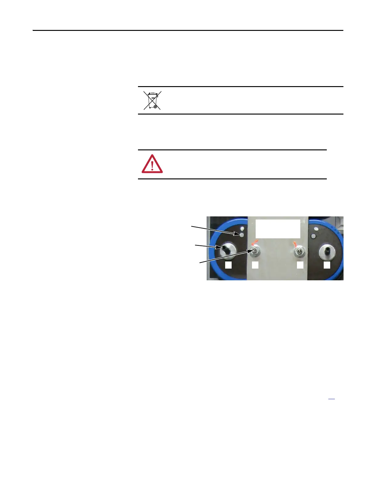
1. Replace set screws for each new Capacitor using a 3 mm angle hex wrench.
Each Capacitor needs a short and long set screw; see the illustration below
for where to install the short and long set screw.
2. Place Capacitors into correct position in drive (vent plug must be at top
or 12 o’clock).
3. Place Bus Capacitor Busbar onto Capacitors.
4. Install washers and nuts onto the shorter set screws to secure the Bus
Capacitor Busbar to the Bus Capacitors.
Note: Install all set screws, washers, and nuts but do not tighten yet.
5. Place the Transitional Busbar in position, but do not install yet. Verify the
Bus Capacitor set screws, Flexible Capacitor Busbars, and all washers and
nuts fit. Adjust as needed.
6. Remove the Transitional Busbar, and tighten all washers and nuts for the
Bus Capacitor Busbar. Torque to 5.6 N•m (50 lb•in).
7. Install the Transitional Busbar according to the instructions on page 33
.
8. Reconnect all wires and connectors.
9. Reassemble remaining components in reverse order.
10. Replace all safety shields and enclosure covers before applying power to the
drive.
ATTENTION: Dispose of the Capacitors properly, in accordance with local
regulations and laws.
ATTENTION: Install each capacitor so its vent plug is at the top or
12 o’clock. Component and system damage may result if you position
any Bus Capacitor incorrectly.
Capacitors shown with
Bus Capacitor Busbar
installed
Vent Plug must be at
top or 12 o’clock
Longer Set Screw for
Transitional Busbar
Shorter Set Screw for
Bus Capacitor Busbar
– + – +

 Loading...


