76 Rockwell Automation Publication 20B-IN026C-EN-P - October 2015
Chapter 3 Inverter Assembly Component Replacement Procedures
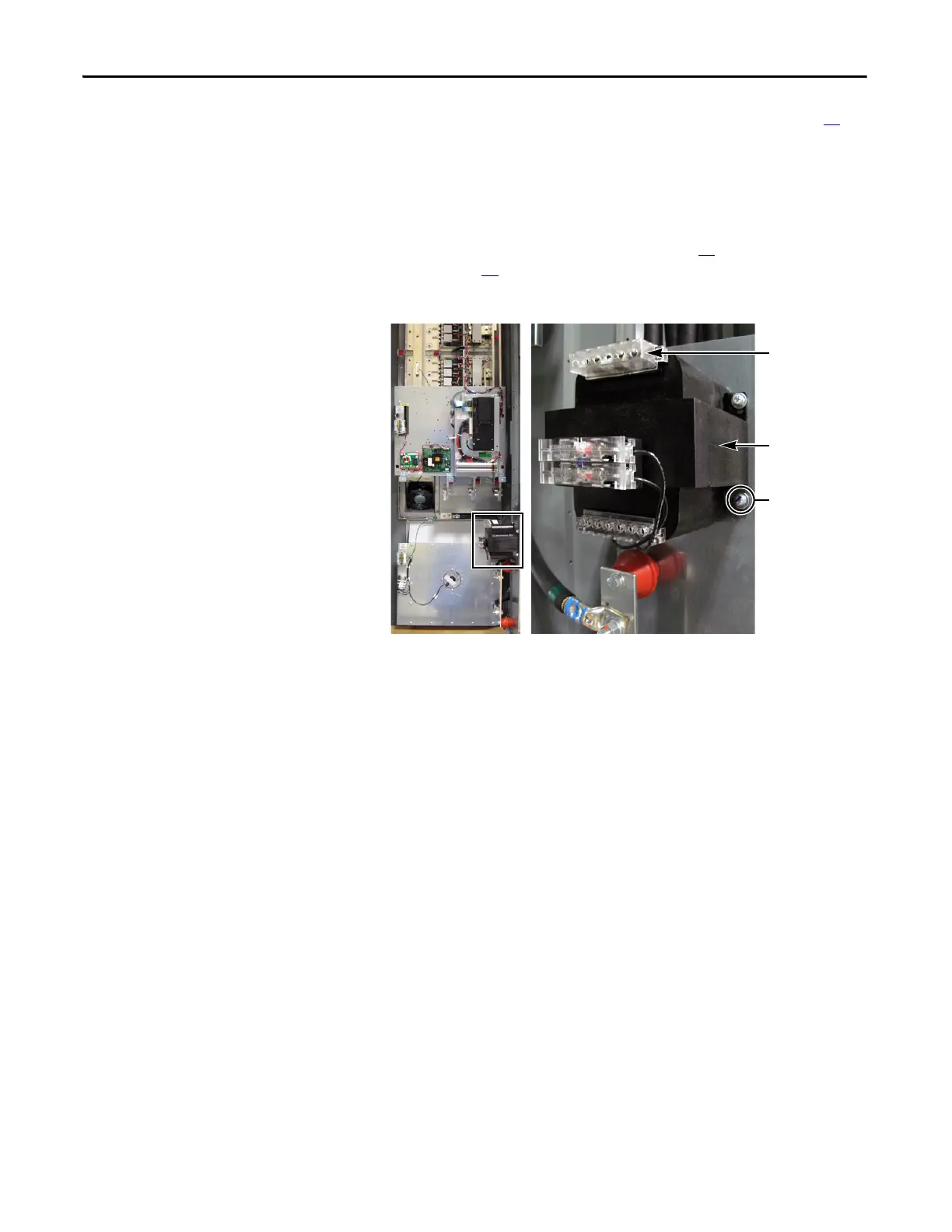
Fan Transformer
(IP20 version only)
See Chapter 1 - Component Diagrams and Torque Specifications on page 15 to
locate components in these instructions.
Remove Components
1. Read and follow the Safety Precautions on page 12 and Important Initial
Steps on page 13
.
2. Remove safety shields and enclosure covers as needed.
3. Label and unplug or disconnect any wires for the Fan Transformer.
4. Unscrew the four transformer mounting bracket screws.
5. Remove the transformer and properly discard.
Install Components
1. Install the new Fan Transformer by screwing mounting brackets to drive.
2. Reconnect all wires for the transformer.
3. Replace all safety shields and enclosure covers before applying power to the
drive.
Fan Transformer
Label and
disconnect any
wires connected
here.
Mounting bracket
screws (4)

 Loading...


