EasyManuals Logo

Allen-Bradley powerflex 700 Installation Instructions

Allen-Bradley powerflex 700
96 pages
To Next Page IconTo Next Page
To Previous Page IconTo Previous Page
Page #75 background imageLoading...
Page #75 background image
Rockwell Automation Publication 20B-IN026C-EN-P - October 2015 75
Inverter Assembly Component Replacement Procedures Chapter 3
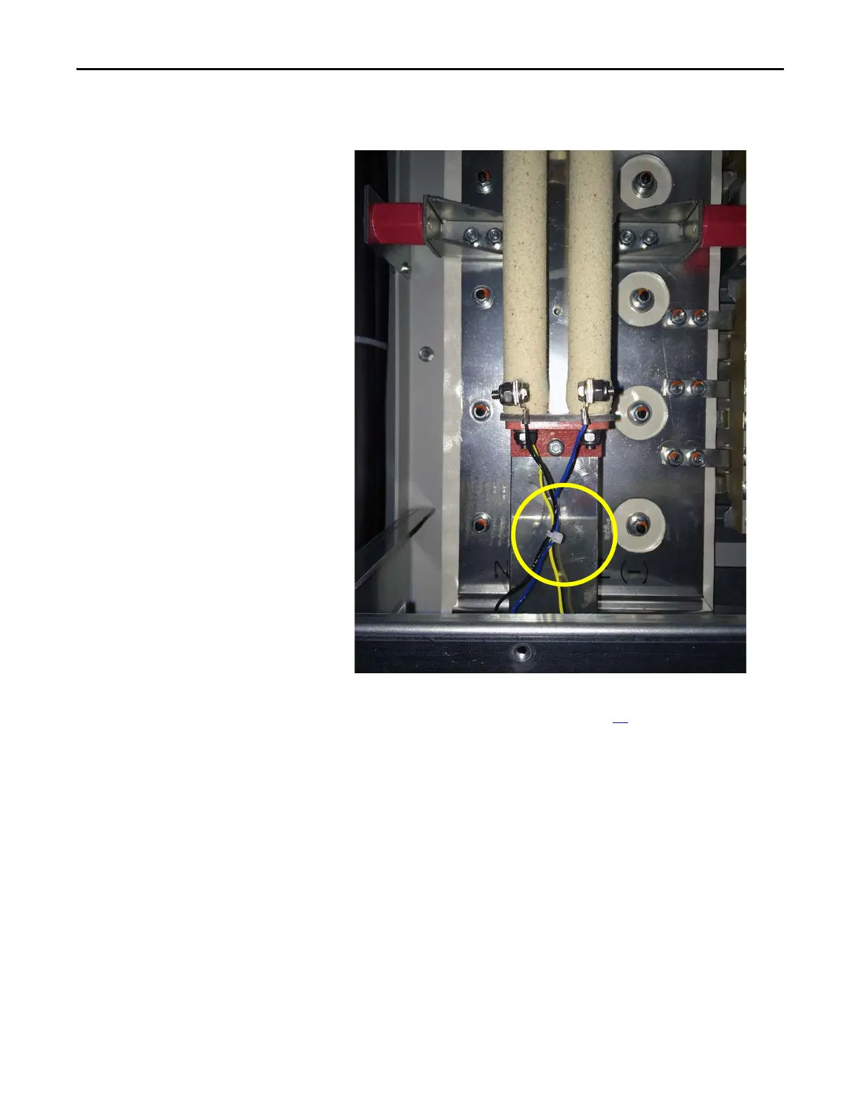
9. Secure the resistor wire bundle below the assembly using tie-wraps (as
shown in the following image).
10. Install the stacking panel as detailed on page 26
.
11. Replace all safety shields and enclosure covers before applying power to the
drive.

Table of Contents

Other manuals for Allen-Bradley powerflex 700

Questions and Answers:

Question and Answer IconNeed help?

Do you have a question about the Allen-Bradley powerflex 700 and is the answer not in the manual?

Allen-Bradley powerflex 700 Specifications

General IconGeneral
SeriesPowerFlex 700
CategoryAC Drive
Input Voltage200-240V AC, 380-480V AC, 500-600V AC
EnclosureType 1
Control MethodSensorless Vector
CommunicationEtherNet/IP, ControlNet, DeviceNet, PROFIBUS DP, Modbus

Related product manuals