88 Rockwell Automation Publication 20B-IN026C-EN-P - October 2015
Chapter 4 Converter Assembly Component Replacement Procedures
Thermal Sensor
The Thermal Sensor system for the Converter Assembly consists of two
sensors. Both sensors have a tripping point of 105 °C (221 °F).
• Sensor TSW1 is located on the upper heatsink
• Sensor TSW2 is located on the lower heatsink
Remove Components
See Thermal Sensor on page 65 for more information.
1. Read and follow the Safety Precautions on page 12
and Important Initial
Steps on page 13
.
2. Remove safety shields and enclosure covers as needed.
3. Cut the wire ties for the wiring harness.
4. Note wire routing and location of Thermal Sensor(s).
5. Remove the mounting screw and star washer for the Thermal Sensor(s).
Note: This screw is small. Take care to not drop or misplace.
The inverter and converter assemblies are separate assemblies. Both
assemblies are included when you order AC input but only the inverter
assembly is included when you order DC input.
If you purchased both units for AC input, then the thermal sensors must be
connected between the two units.
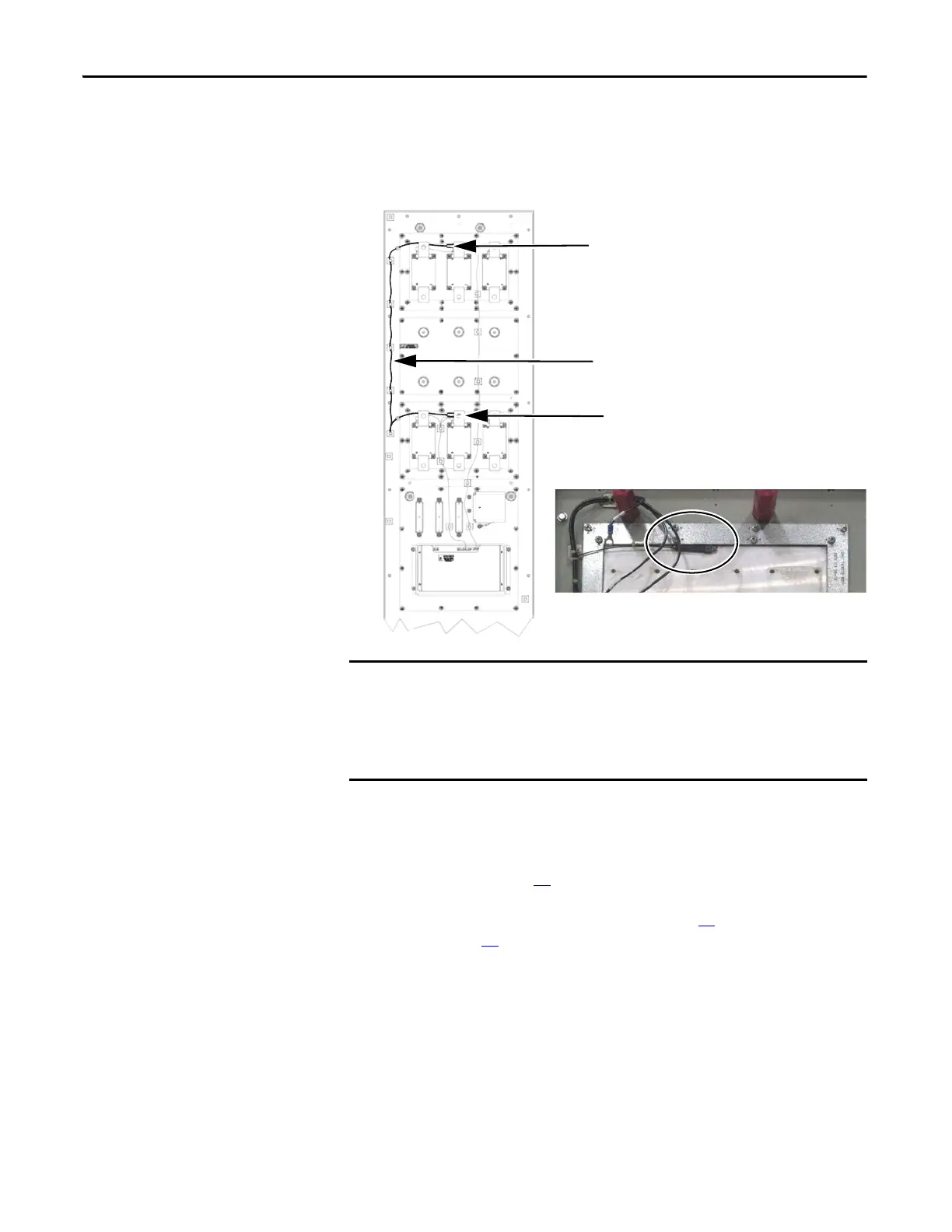
TSW1 Thermal Sensor
TSW2 Thermal Sensor
The thermal sensors are wired in tandem and are
connected to the J6 connector on the Power Interface
Board on the Inverter.
Thermal Sensor shown mounted on Heatsink with SCR
Modules and Busbars removed.

 Loading...


