EasyManuals Logo

Allen-Bradley powerflex 700 Installation Instructions

Allen-Bradley powerflex 700
96 pages
To Next Page IconTo Next Page
To Previous Page IconTo Previous Page
Page #44 background imageLoading...
Page #44 background image
44 Rockwell Automation Publication 20B-IN026C-EN-P - October 2015
Chapter 3 Inverter Assembly Component Replacement Procedures
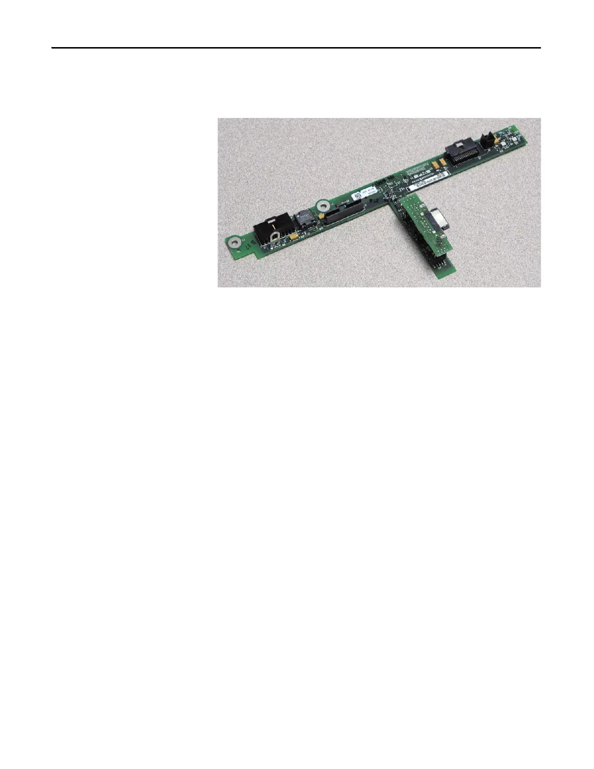
Install Components
1. Install the new T-Comm Board.
2. Verify the board is locked into all seven locking tabs.
3. Carefully bend the T-Comm grounding tab until it is flush with the screw
mount on the Main Control Board.
4. Reassemble all components in the reverse order of removal.
5. Tighten the HIM Cradle/Board mounting screws.
6. Reconnect all cables, safety shields, and enclosure covers before applying
power to the drive.

Table of Contents

Other manuals for Allen-Bradley powerflex 700

Questions and Answers:

Question and Answer IconNeed help?

Do you have a question about the Allen-Bradley powerflex 700 and is the answer not in the manual?

Allen-Bradley powerflex 700 Specifications

General IconGeneral
SeriesPowerFlex 700
CategoryAC Drive
Input Voltage200-240V AC, 380-480V AC, 500-600V AC
EnclosureType 1
Control MethodSensorless Vector
CommunicationEtherNet/IP, ControlNet, DeviceNet, PROFIBUS DP, Modbus

Related product manuals