Rockwell Automation Publication 20B-IN026C-EN-P - October 2015 43
Inverter Assembly Component Replacement Procedures Chapter 3
4. Remove the 20-COMM-C Board (if used):
a. Disconnect the ribbon cable between the 20-COMM-C Board and
T-Comm board; disconnect only from the T-Comm board.
b. Remove and save the four mounting screws.
5. If the 20-COMM-C Board is not used, remove the screw securing the
T-Comm grounding tab.
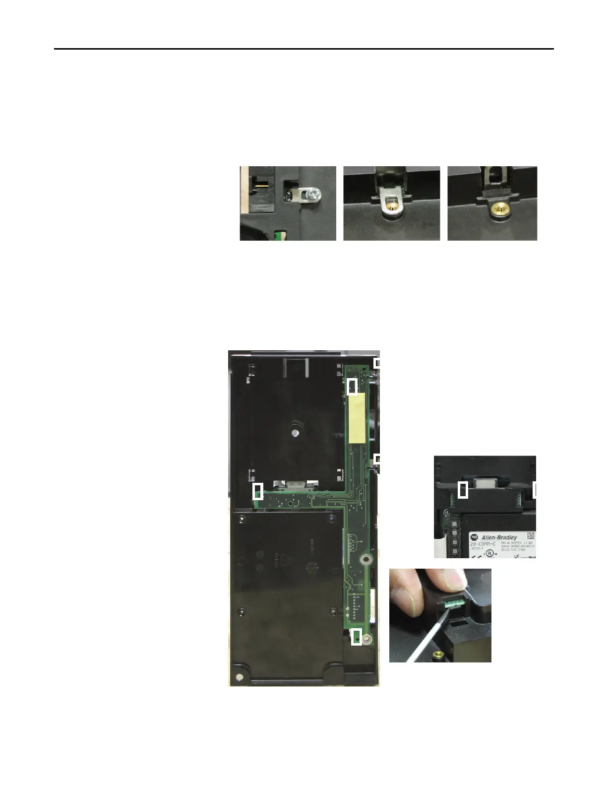
6. Place the tip of a flathead screwdriver between the T-Comm grounding tab
and screw mount. Gently pry up until the grounding tab is in an upright
position, or about 90 degrees from the screw mount.
7. If needed, use the same flathead screwdriver tip to pry the seven locking
tabs away from the T-Comm Board.
8. Remove the T-Comm Board from the HIM Cradle/Board; return or
dispose of it properly.
T-Comm grounding tab screw T-Comm grounding tab flat T-Comm grounding tab upright
T-Comm Board Locking Tab Locations
Five locking tabs are on the back side of the Main
Control Board (left); two are on the front side in the
area between the optional HIM and 20-COMM-C board
slots (below).
Use a flathead screwdriver tip to pry the
locking tabs away from the T-Comm Board
(above).

 Loading...


