Rockwell Automation Publication 20B-IN026C-EN-P - October 2015 37
Basic Component Removal Procedures Chapter 2
11. Remove the two bolts, washers, and nuts that secure each AC Busbar to
the SCR Modules, and save.
12. Remove the two set screw nuts that secure each AC Busbar to the glastic
standoffs and save.
13. Remove each AC Busbar.
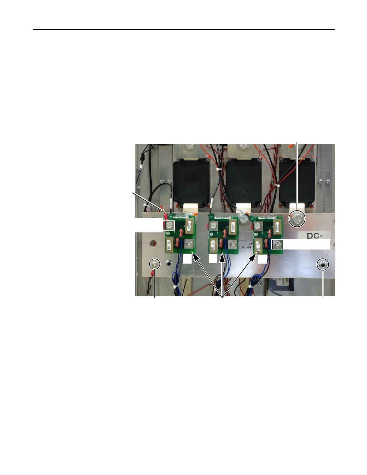
14. Carefully label and disconnect all wiring to the three snubber boards on
the DC– Busbar.
15. Remove the R phase Snubber Board.
Keep the mounting bolt in the S and T phase snubber boards.
16. Label the wire and remove the screw for the Precharge Board J1 (black)
terminal wire, and save.
17. Remove the three bolts, washers, and nuts that secure the DC– Busbar to
the SCR Modules, and save.
18. Remove the two set screw nuts that secure the DC– Busbar to the glastic
standoffs and save.
19. Remove the DC– Busbar.
Set Screw Nut (2) for
Glastic Standoffs
Precharge Board J1 Black Terminal Wire
Mounting Bolts to SCR Modules (3)
R
S
T
Snubber Boards
T
Mounting Bolt (3)
DC1 Terminal Black Wires to
DC+ Busbar, (3)
Precharge Board J1
Red Wire

 Loading...


