EasyManuals Logo

Allen-Bradley powerflex 700 Installation Instructions

Allen-Bradley powerflex 700
96 pages
To Next Page IconTo Next Page
To Previous Page IconTo Previous Page
Page #32 background imageLoading...
Page #32 background image
32 Rockwell Automation Publication 20B-IN026C-EN-P - October 2015
Chapter 2 Basic Component Removal Procedures
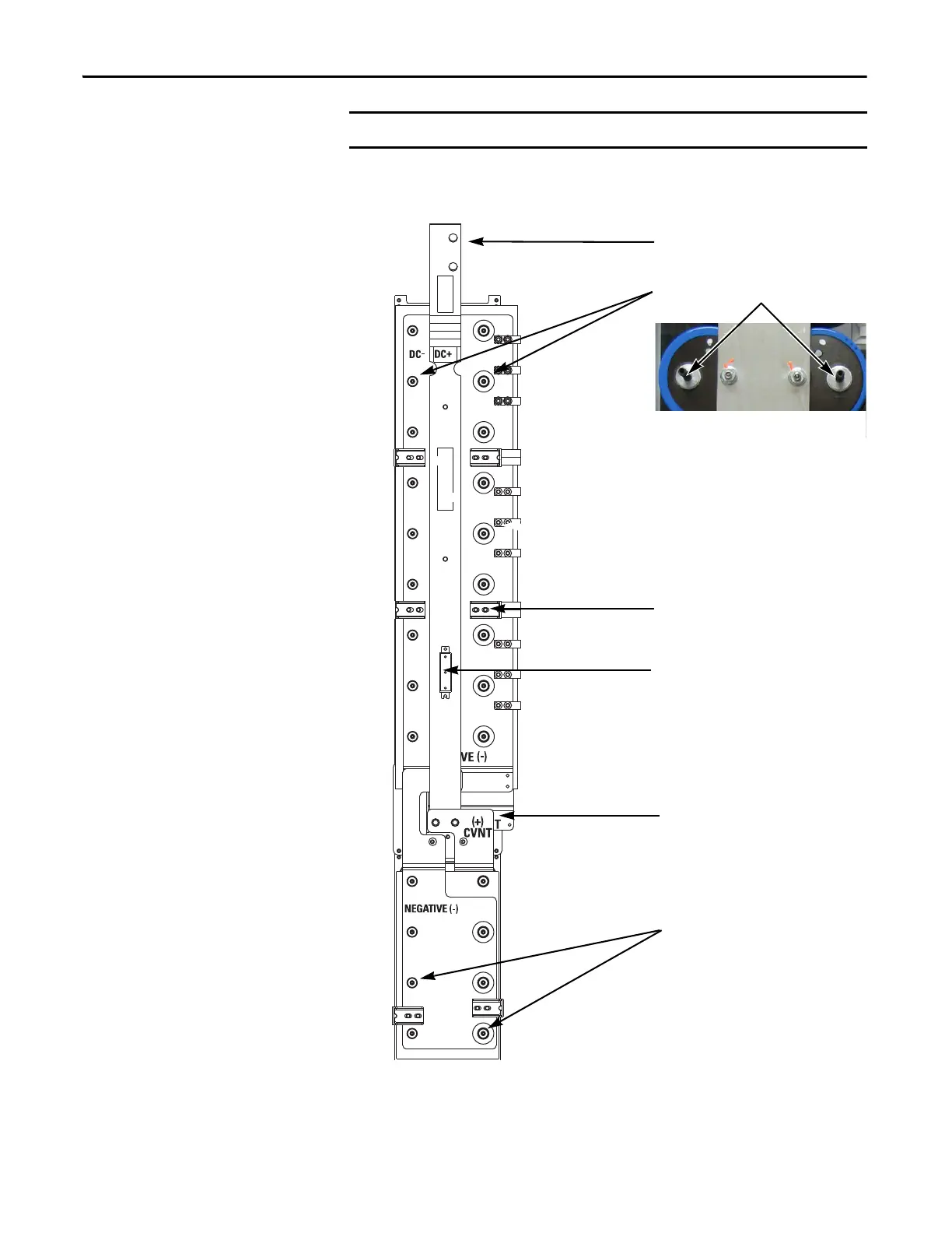
15. Remove the Transitional Busbar assembly.
IMPORTANT
Set screws may come out with the nuts. Save all nuts and set screws.
Upper Capbus Support Nuts (18)
attached to Set Screws
Side Standoffs and Brackets (6)
DC Choke Output Cables
Note: Photo shows set screws in
Capacitors; these set screws may come out with
the Transitional Busbar assembly nuts when they
are removed.
Lower Capbus Support Nuts (8)
attached to Set Screws
Upper and Lower Capbus Support
Connecting Brackets
Balancing Resistor
(Old Style Resistor Shown)

Table of Contents

Other manuals for Allen-Bradley powerflex 700

Questions and Answers:

Question and Answer IconNeed help?

Do you have a question about the Allen-Bradley powerflex 700 and is the answer not in the manual?

Allen-Bradley powerflex 700 Specifications

General IconGeneral
SeriesPowerFlex 700
CategoryAC Drive
Input Voltage200-240V AC, 380-480V AC, 500-600V AC
EnclosureType 1
Control MethodSensorless Vector
CommunicationEtherNet/IP, ControlNet, DeviceNet, PROFIBUS DP, Modbus

Related product manuals