Rockwell Automation Publication 20B-IN026C-EN-P - October 2015 31
Basic Component Removal Procedures Chapter 2
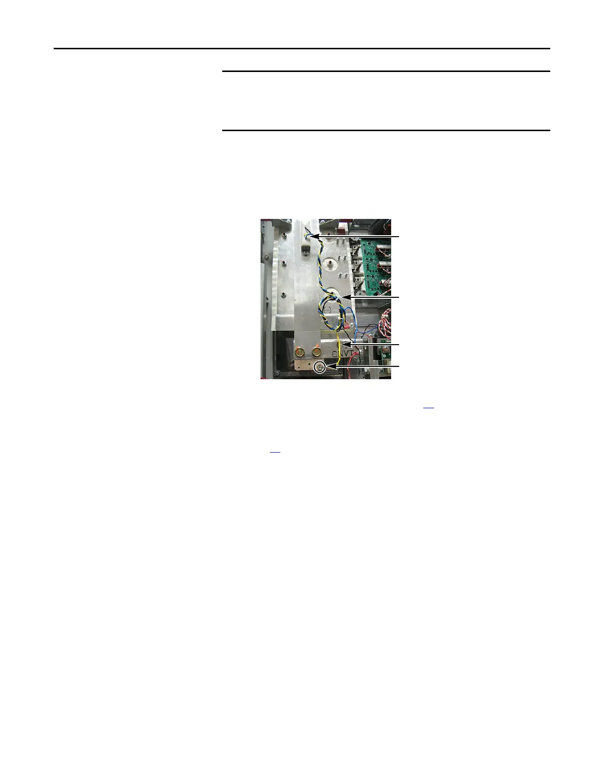
10. Cut tie wraps for the Balancing Resistor wiring.
11. Disconnect the yellow wire for the Balancing Resistor.
You do not need to disconnect the blue and black wires.
12. Label and disconnect all other wires attached to the Busbar.
13. Remove the six side standoffs and brackets (four upper and two lower) for
the Transitional Busbar assembly (see page 32
).
14. Remove the upper Capbus Support nuts and the lower Capbus Support
nuts fastening the Transitional Busbar assembly to the Bus Capacitors (see
page 32
).
The positive (DC+) Flexible Capacitor Busbars are connected to the back
side of the Transitional Busbar assembly. The Transitional Busbar assembly
must be removed before the DC+ Flexible Capacitor Busbars can be
accessed and removed.
Balancing Resistor yellow wire
Disconnect here
Resistor wiring tie wraps
Balancing Resistor
(Old Style Resistor Shown)

 Loading...


