40 Rockwell Automation Publication 20B-IN026C-EN-P - October 2015
Chapter 3 Inverter Assembly Component Replacement Procedures
Main Control Board (version
2.0)
See Chapter 1 - Component Diagrams and Torque Specifications on page 15 to
locate components in these instructions.
Remove Components
1. Read and follow the Safety Precautions on page 12 and Important Initial
Steps on page 13
.
2. Remove safety shields and enclosure covers as needed.
3. Unscrew the green/yellow ground wire from the Communications Panel.
4. Remove the nuts, screws, and washers (two each) that secure the
Communications Panel to the Main Control Panel.
5. Disconnect the ribbon cable that connects the Human Interface Module
(HIM) Cradle/Board to the Main Control Board.
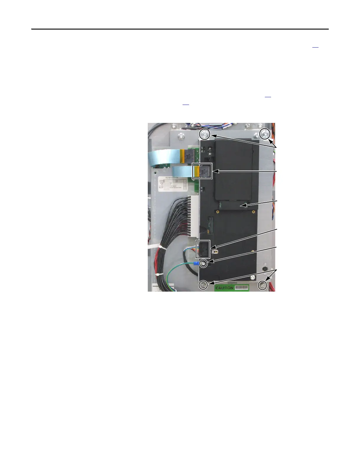
6. Securely hold the Communications Panel and release the cable from the
DPI Port 2 clamp. Set the Communications Panel aside.
Screw for green/yellow
Ground Wire
Cable at DPI Port 2 Clamp
Communication Panel
Mounting Nuts (2)
Communication Panel
Mounting Screws and
Washers (2 each)
HIM Cradle/Board
(Located over
Main Control Board)
Ribbon Cable
from T-Comm Board (J3)
to Main Control Board (J3)

 Loading...


