EasyManuals Logo

Allen-Bradley powerflex 700 Installation Instructions

Allen-Bradley powerflex 700
96 pages
To Next Page IconTo Next Page
To Previous Page IconTo Previous Page
Page #82 background imageLoading...
Page #82 background image
82 Rockwell Automation Publication 20B-IN026C-EN-P - October 2015
Chapter 4 Converter Assembly Component Replacement Procedures
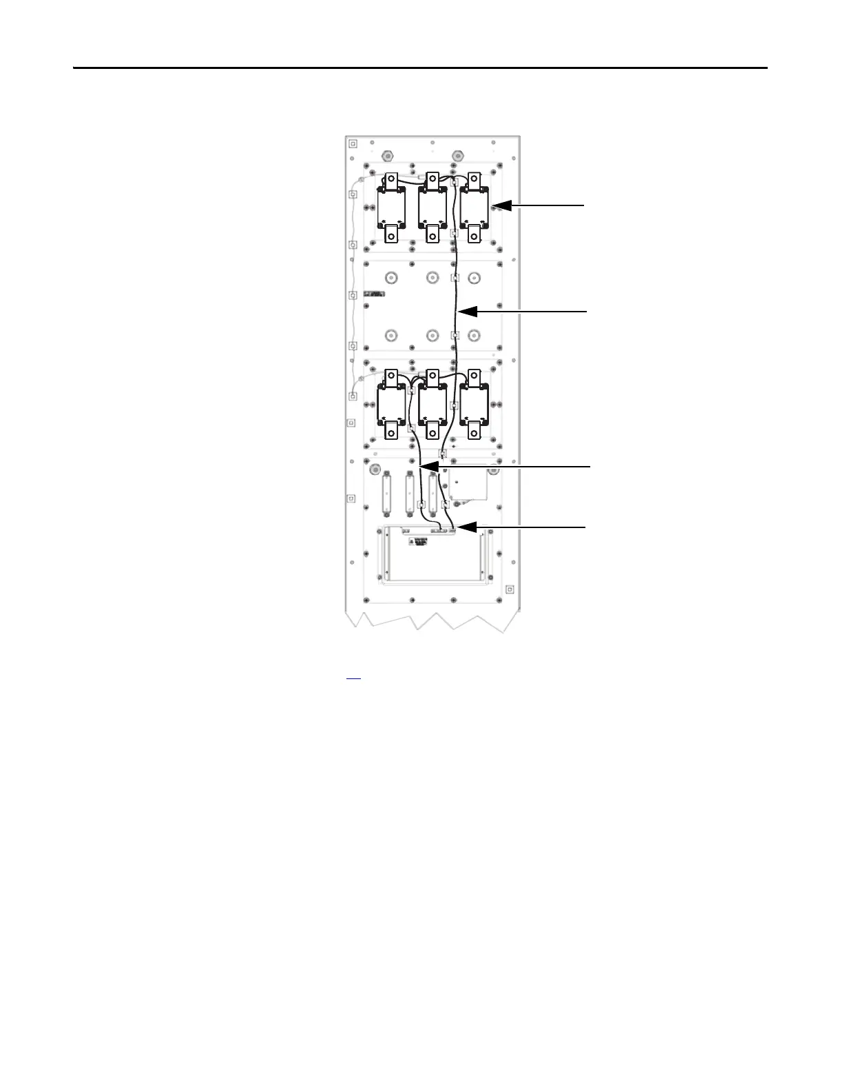
6. Reinstall the Precharge Board wires to the MOV modules.
7. Reinstall the busbars and all Busbar wires. See Install Components on page
38
.
8. Reinstall the DC cables. Torque DC cable screws to 12.2 N•m (108 lb•in).
9. Reassemble remaining components in reverse order.
10. Replace all safety shields and enclosure covers before applying power to the
drive.
Red and White Wires from Upper SCR
Modules to J2 on the Precharge
Board
Red and White Wires from Lower SCR
Modules to J3 on the Precharge
Board
SCR Modules (6) Installed with
Wiring Plug Facing the top of the
chassis.
J3 and J2 on the Precharge Board

Table of Contents

Other manuals for Allen-Bradley powerflex 700

Questions and Answers:

Question and Answer IconNeed help?

Do you have a question about the Allen-Bradley powerflex 700 and is the answer not in the manual?

Allen-Bradley powerflex 700 Specifications

General IconGeneral
SeriesPowerFlex 700
CategoryAC Drive
Input Voltage200-240V AC, 380-480V AC, 500-600V AC
EnclosureType 1
Control MethodSensorless Vector
CommunicationEtherNet/IP, ControlNet, DeviceNet, PROFIBUS DP, Modbus

Related product manuals