Rockwell Automation Publication 20B-IN026C-EN-P - October 2015 81
Converter Assembly Component Replacement Procedures Chapter 4
Install Components
1. Use isopropyl alcohol to thoroughly clean the Heatsink mounting surface
where the SCR modules will be installed.
2. Verify the mounting surface of the new SCR module is clean. If not, clean
with isopropyl alcohol.
3. Use a 3- or 4-inch paint roller or putty knife to apply a thin, even coating of
the supplied thermal grease to the mounting surface of each SCR module.
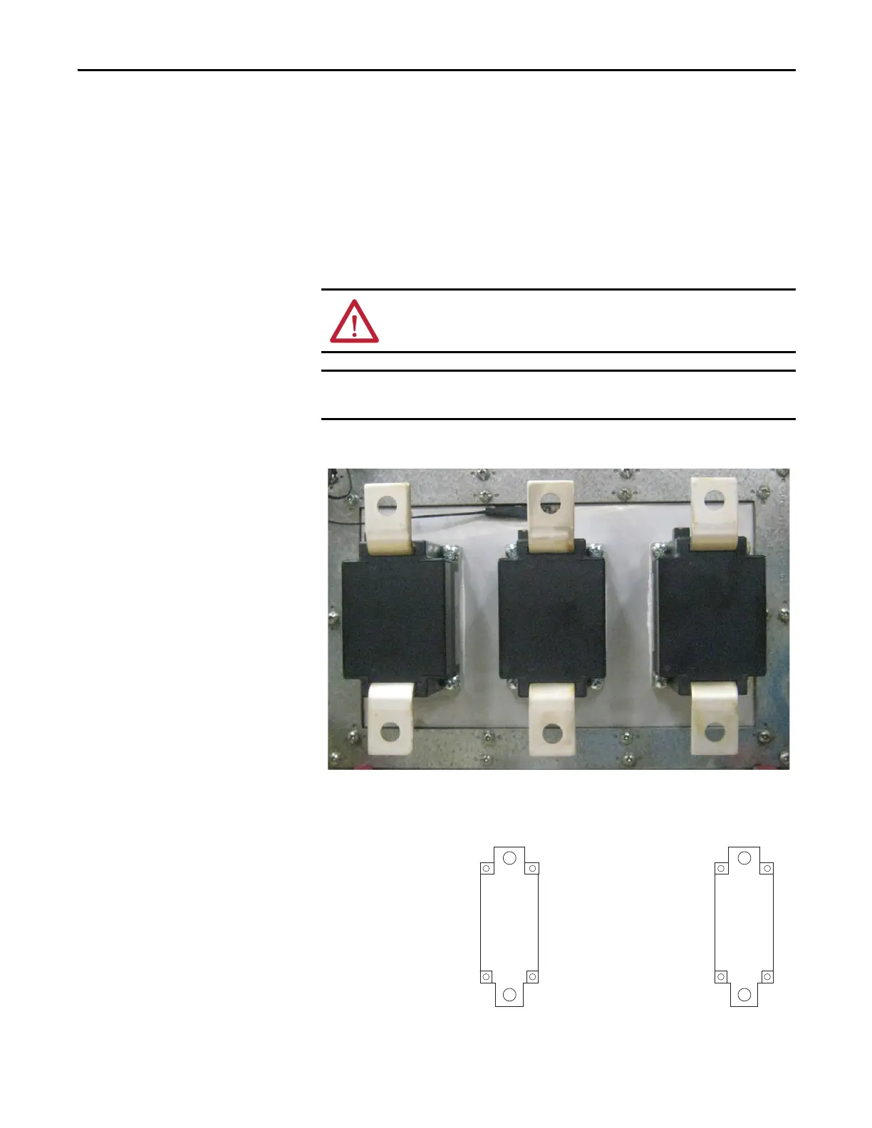
4. Position the SCR modules on the heatsink.
5. Install the SCR module with supplied screws and torque using the
sequences and specifications shown in the diagram below.
In the next step, be sure to properly install the SCR modules as shown. If
you install the SCR modules incorrectly, they will not work.
In the next step, take care to not disturb any of the thermal grease on the
SCR module.
➊➌
➍➋
First Torque Sequence:
0.7 N•m (6.0 lb•in)
Final Torque Sequence:
5.6 N•m (50 lb•in)

 Loading...


