7–1
1Wiring Your I/O Modules
Publication
1747-6.2
Installing the RTB
Below are guidelines for installing the RTB.
1. Be sure the color of the RTB matches the color band on the
module.
!
ATTENTION: Inserting a wired RTB on an incorrect
module can damage the module circuitry when power
is applied.
2. Write the appropriate slot, chassis, and module type on the RTB
label.
!
ATTENTION: Disconnect power before attempting
to install or remove I/O modules or their terminal
blocks.
3. Disconnect power.
4. Align the terminal block release screws with the mating
connector in the module.
5. Press the RTB firmly onto the connector contacts.
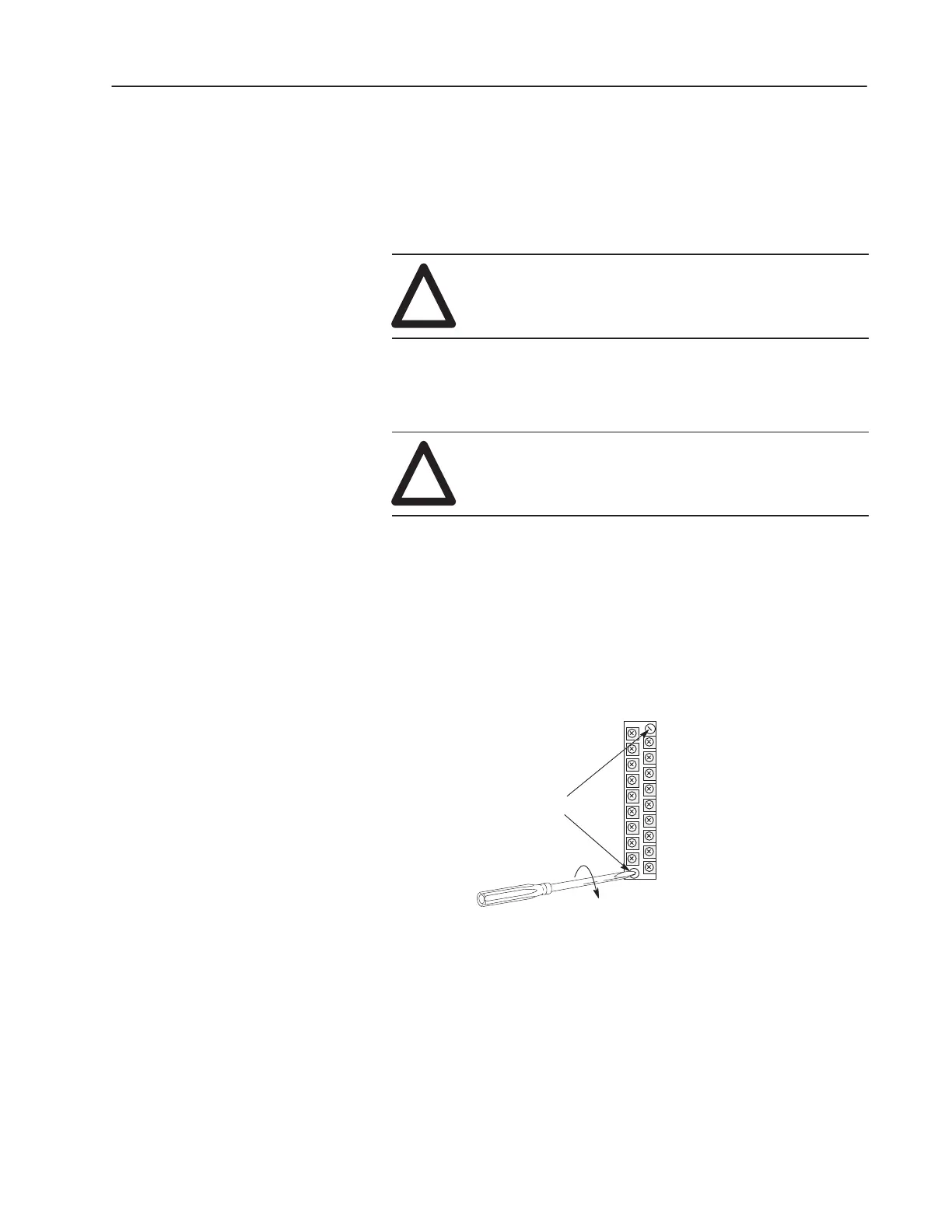
6. Tighten the terminal block release screws. To avoid cracking the
terminal block, alternate the tightening of the screws.
Terminal Block Release Screws
Maximum Torque=0.7–0.9 Nm
(6–8 in./lbs.)

 Loading...


