EasyManuals Logo

Allen-Bradley SLC 500 Installation And Operation Manual

Allen-Bradley SLC 500
244 pages
To Next Page IconTo Next Page
To Previous Page IconTo Previous Page
Page #154 background imageLoading...
Page #154 background image
10–28
Troubleshooting
Publication
1747-6.2
The following will assist you in troubleshooting your output
modules.
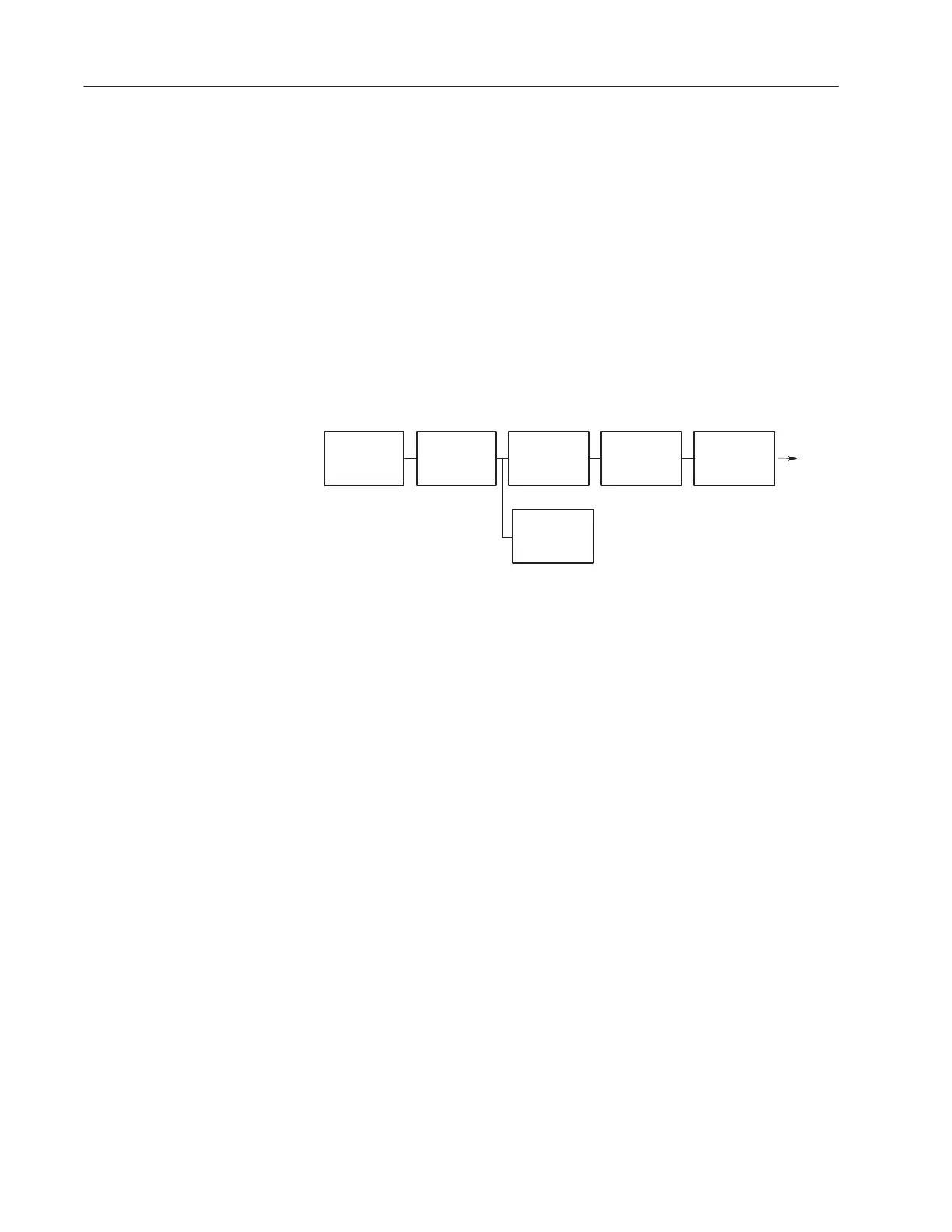
Output Circuit Operation
An output circuit controls the output signal in the following manner:
1. Logic circuits determine the output status.
2. An output LED indicates the status of the output signal.
3. Opto-electrical isolation separates output circuit logic and
backplane circuits from field signals.
4. The output driver turns the corresponding output on or off.
Backplane
Opto-
Electrical
Isolation
Logic Circuits Output Drivers
LED
Logic Circuits Output
Troubleshooting Your
Output Modules

Table of Contents

Other manuals for Allen-Bradley SLC 500

Questions and Answers:

Question and Answer IconNeed help?

Do you have a question about the Allen-Bradley SLC 500 and is the answer not in the manual?

Allen-Bradley SLC 500 Specifications

General IconGeneral
Programming SoftwareRSLogix 500
Communication PortsRS-232, DH-485, DH+
Power Supply120/240V AC or 24V DC
Programming LanguagesLadder Logic
Operating Temperature0°C to 60°C (32°F to 140°F)
Relative Humidity5% to 95% (non-condensing)
Memory4K to 64K words (depending on the processor)

Related product manuals