10–25
Troubleshooting
Publication
1747-6.2
Returning the SLC 5/03, SLC 5/04, and SLC 5/05 Processors to
“Initial Factory Conditions”
We only recommend this procedure if the communication channels
have been shut down due to the configuration parameters, or if you
absolutely cannot establish communications with the processor.
!
ATTENTION: If you return the processor to the
initial factory conditions, the user program and
communication configurations are returned to their
default settings.
To do this:
1. Remove power from the SLC 500 power supply.
2. Remove the processor from the chassis.
3. Disconnect the battery by removing the battery connector from its
socket.
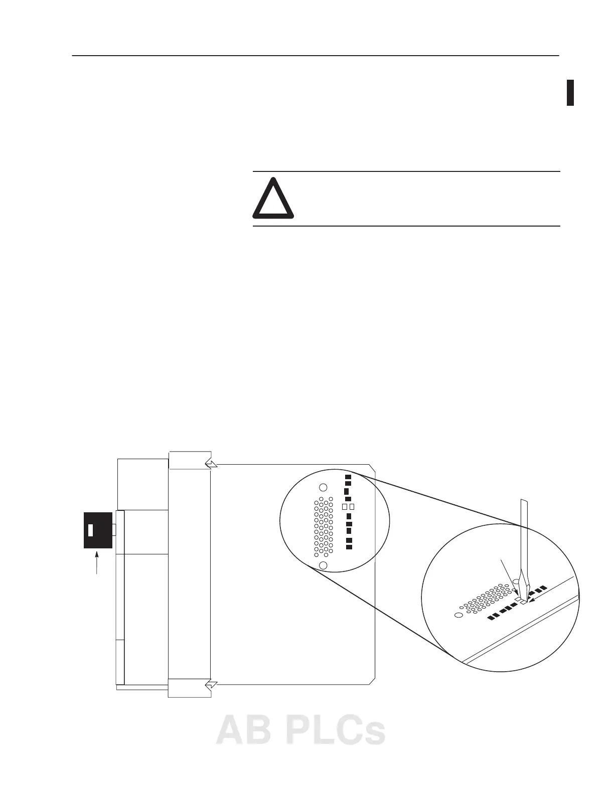
4. Locate the VBB and GND connections on the right side of the
motherboard.
5. Place a small bladed screwdriver across the VBB and GND
connections and hold for 60 seconds. This returns the processor
to the initial factory conditions.
Right Side View
Keyswitch
GND
VBB
Mother Board
Mother Board
VBB
GND
SLC 5/03 (1747-L531 and 1747-L532)
AB PLCs

 Loading...


