6–8
Installing Your Hardware Components
Publication
1747-6.2
If you have multiple chassis configurations, install the chassis
interconnect cable before installing the power supply.
(See page 6–10.) Also, the power supply terminals accept two #14
AWG wires and are marked as shown in the figure on page 6–8. To
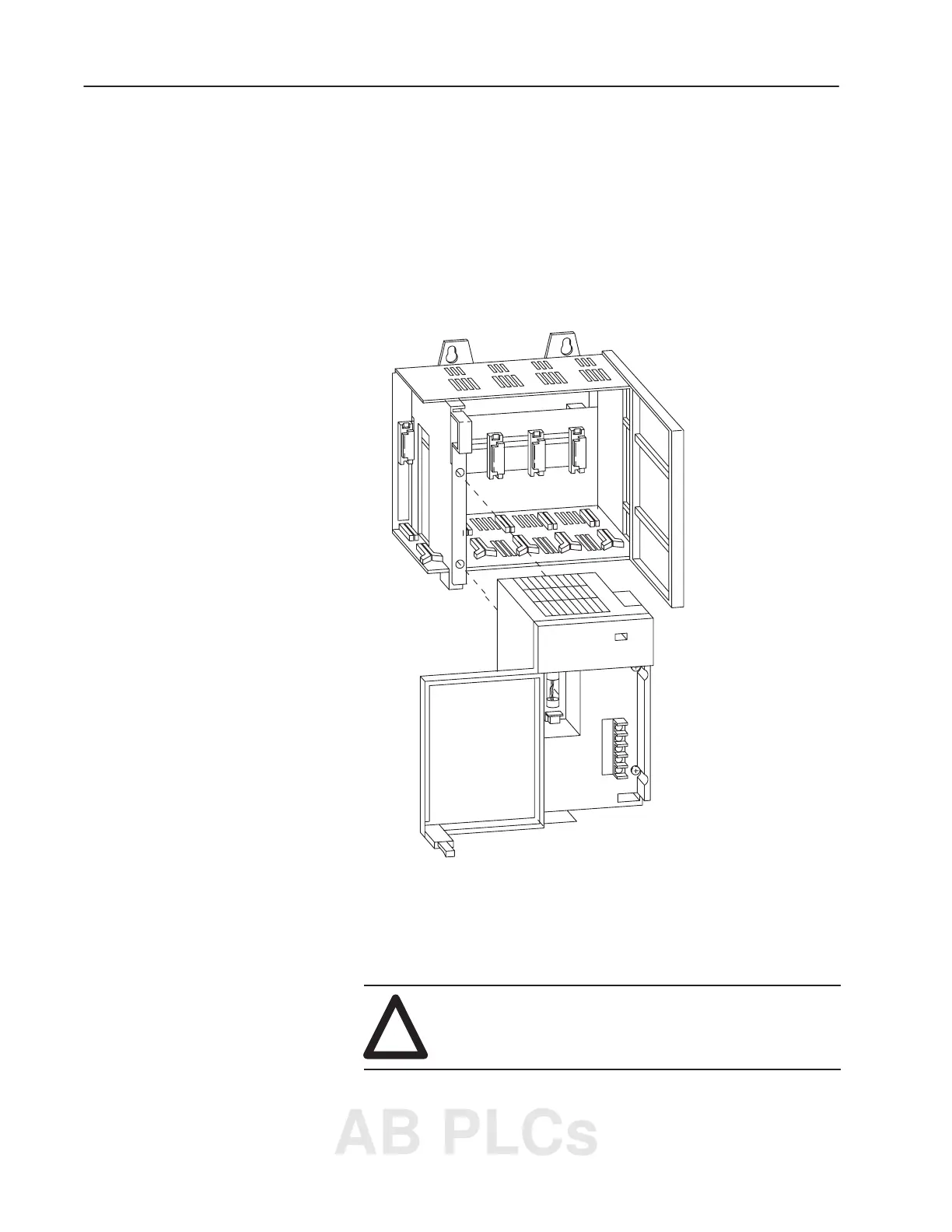
install the power supply, do the following:
1. Align the circuit board with the card guide on the left side of the
chassis. Slide the power supply in until flush with the chassis.
19524
2. Fasten the power supply to the chassis with the two Phillips head
screws.
3. Place the jumper to match the input voltage. (This does not apply
to 1746-P3 or 1746-P5, which do not have a jumper.)
!
ATTENTION: Make jumper selection before
applying power. Hazardous voltage is present on
exposed pins when power is applied.
Installing Your Power
Supply
AB PLCs

 Loading...


