9–5
Maintaining Your Control System
Publication
1747-6.2
Your SLC 5/03, SLC 5/04, or SLC 5/05 processor provides back-up
power for RAM through a replaceable lithium battery. This battery
provides back-up for approximately 2 years. A BATT LED on the
front of the processor alerts you when the battery voltage has fallen
below a threshold level.
To replace the lithium battery follow these steps:
!
ATTENTION: Do not remove the processor from the
SLC 500 chassis until all power is removed from the
SLC 500 power supply.
1. Remove power from the SLC 500 power supply.
2. Remove the processor from the chassis by pressing the retainer
clips at both the top and bottom of the module and slide it out.
!
ATTENTION: Do not expose the processor to
surfaces or other areas that may typically hold an
electrostatic charge. Electrostatic charges can alter or
destroy memory.
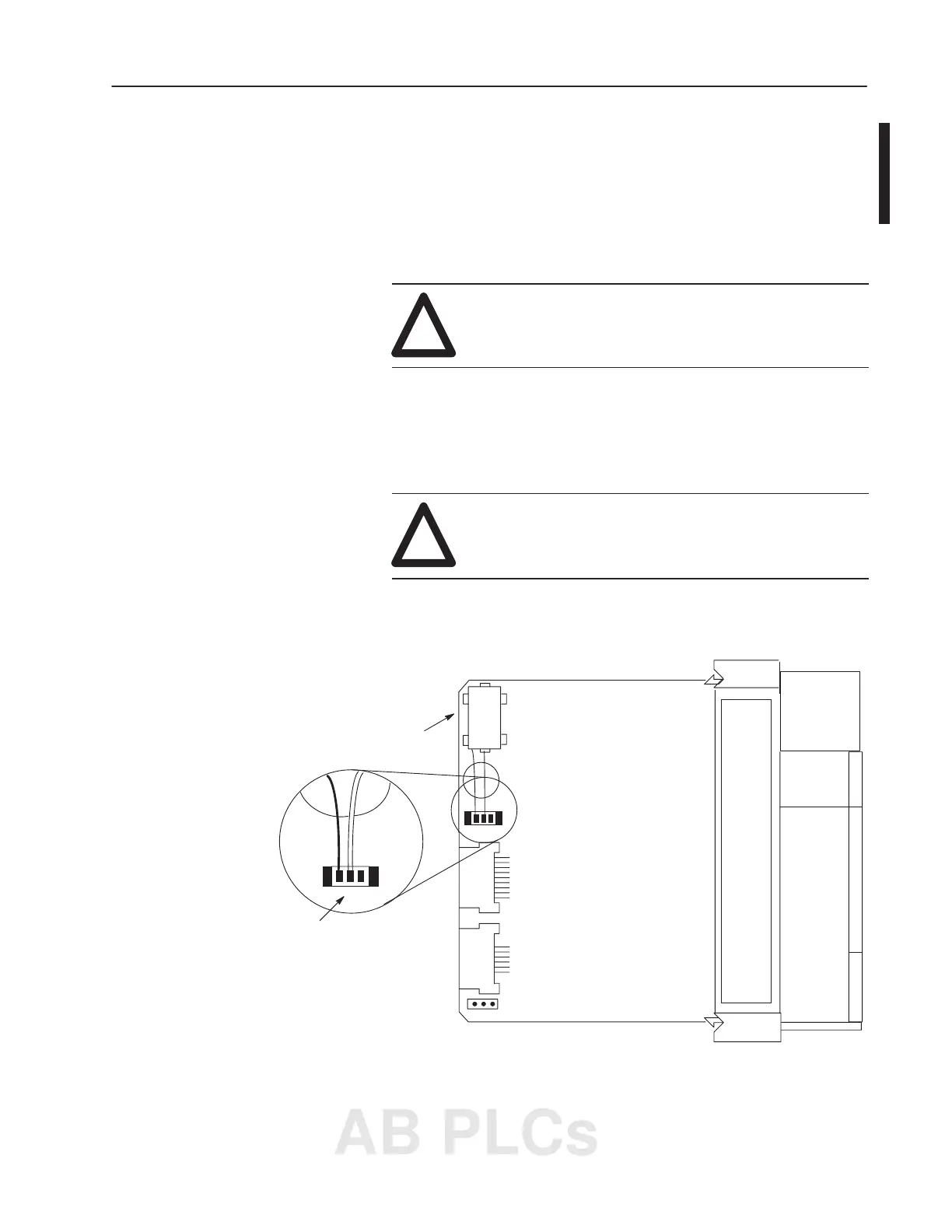
3. Unplug the battery connector. Refer to the figure below for
battery connector location.
Left Side View
Battery
Red
White
Battery
Connector
Replacing Your SLC 5/03,
SLC 5/04, or SLC 5/05
Battery
AB PLCs

 Loading...


