A–10 Setting Up the DH-485 Network
Publication
1747-6.2
Important: The SLC 500 Series A (only) processors set the
maximum node address to 31 when power is cycled
increasing initialization and response time of the
network.
Maximum
Number of Communicating Devices
SLC 500 fixed and SLC 5/01 processors can be selected by two
initiators maximum at the same time. Using more than two initiators
to select the same SLC 500 fixed and SLC 5/01 processors at the
same time can cause communication timeouts.
To install a DH-485 network, you will need tools to strip the shielded
cable and to attach the cable and terminators to the Isolated Link
Coupler.
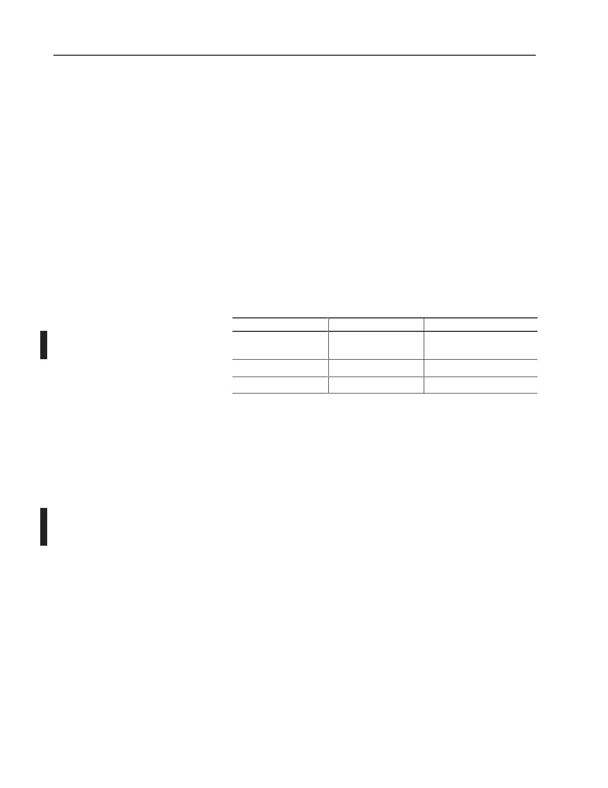
Install the DH-485 network using the following tools (or equivalent):
Description Part Number Manufacturer
Shielded Twisted Pair
Cable
Belden #3106A or #9842 Belden
Stripping Tool 45-164 Ideal Industries
1/8 ” Slotted Screwdriver Not Applicable Not Applicable
DH-485 Communication Cable and Isolated Link Coupler
The link coupler provides a connection for each node. The isolated
link coupler electrically isolates the DH-485 communication
interface from the processor and peripheral connections.
Electrical-optical isolation is provided to 1500V.
The suggested DH-485 communication cable is Belden #3106A or
#9842 cable. The cable is jacketed and shielded with two twisted
wire pairs and a drain wire.
One pair provides a balanced signal line, and one wire of the other
pair is used for a common reference line between all nodes on the
network. The shield reduces the effect of electrostatic noise from the
industrial environment on the network communication.
Installing the DH-485 Communication Cable
The communication cable consists of a number of cable segments
daisy-chained together. The total length of the cable segments
cannot exceed 1219 m (4000 ft).
Installing the DH-485
Network

 Loading...


