2–2
Selecting Your Hardware Components
Publication
1747-6.2
The SLC 500 programmable controller has features that previously
could only be found in large programmable controllers. It has the
flexibility and power of a large controller with the size and simplicity
of a small controller. The SLC 500 controller offers you more
control options than any other programmable controller in its class.
These programmable controllers make up a technologically advanced
control system having inherent flexibility and advantages
characteristic of other programmable controllers, but with one
important difference — simplicity!
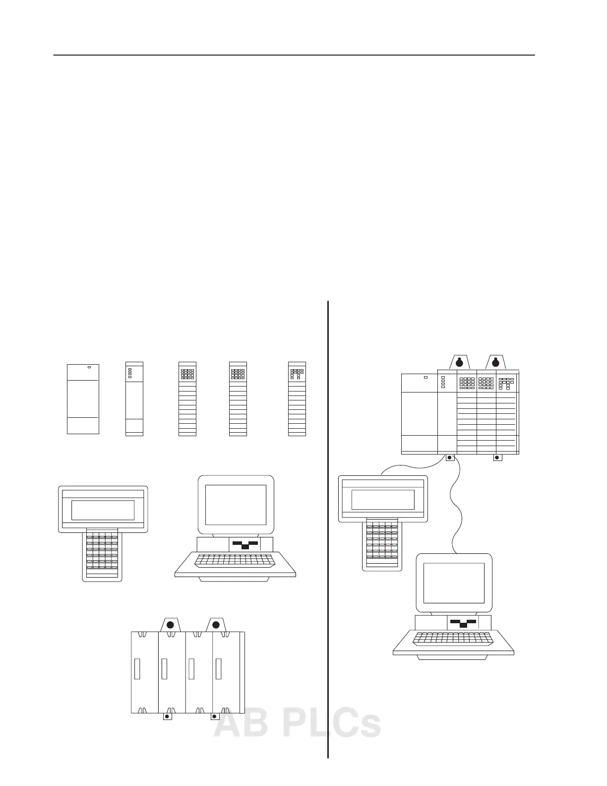
The basic modular controller consists of a chassis, power supply,
processor (CPU), Input/Output (I/O modules), and an operator
interface device for programming and monitoring. The figure below
shows typical hardware components for a modular controller.
Chassis
Power Supply
Processor
Module
Input Module
Output Module
Programming Terminal
Modular Controller
Modular Hardware Components
Programming PC
OR
Combination
I/O Module
h
Y
SLC 500
Controller Can Do for You
w
Y
Control System
AB PLCs

 Loading...


