3–9
System Installation Recommendations
Publication
1747-6.2
!
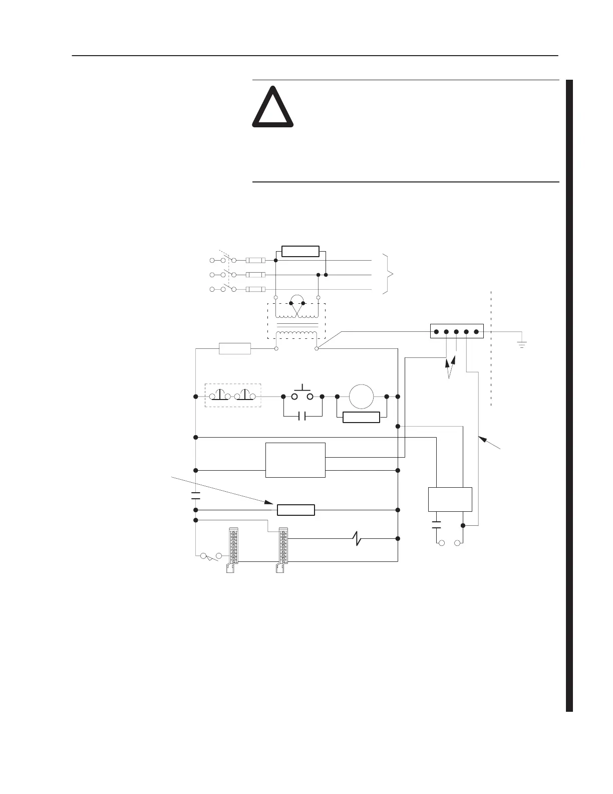
ATTENTION: Your SLC 500 power supply can be
damaged by voltage surges when switching inductive
loads such as motors, motor starters, solenoids, and
relays. To avoid damage to your SLC 500 power
supply in these applications, it is strongly
recommended that an isolation transformer be used to
isolate the power supply from harmful voltage surges.
Grounded ac Power-Distribution System with Master-Control Relay
Enclosure
+-
Wall
Back-panel
Step-down
Transformer
FUSE
Multiple E-stop switches
Start
CRM
Grounded Conductor
Connect
when applicable
Grounding-electrode
Conductor to
Grounding-electrode
System
Equipment-
Grounding
Conductors
T
o DC I/O
actuators/
CRM
User DC
Supply
Output Module
Wiring
Arm
Output
Actuator
Input
Module
Wiring
Arm
Input
Sensor
CRM
Controller
Power Supply
L1
N or L2
GND
CRM
sensors
X
1
X
2
1FU
L1
2FU
L2
3FU
L3
L1
L2
L3
T
o Motor
Incoming
Disc.
Starters
AC
H
1
H
2
H
3
H
4
Ground Bus
The I/O circuits form a net
inductive load switched by the
CRM contacts. Therefore, a
suppressor is needed
across the line at the load
side of the CRM contacts.
Suppressor
Suppressor
1
Suppressor
➄
➃
➂
➁
➀
➀
To
minimize EMI generation, connect a suppressor across an inductive load. For more information on selecting surge suppressors, see page 2–24.
➁
Contact motor manufacturer for recommended surge supression for motors.
➂
In applications where severe energy is re-generated by motors when power is removed, use an isolation/constant-voltage transformer in place of the step-down
transformer.
➃
In many applications, a second transformer provides power to the input circuits and power supplies for isolation from the output circuits.
➄
Connect a suppressor here to minimize EMI generation from the net inductive load switched by the CRM contacts. For more information on selecting surge
suppressors, see page 2–24.

 Loading...


