Chapter 4
Publication
1747-6.2
Mounting Your SLC 500
Control System
This chapter provides mounting dimensions for:
• 4, 7, 10, and 13-slot chassis
• link coupler (AIC)
• Data Terminal Access Module (DTAM)
• DTAM Plus Operator Interface
• DTAM Micro Operator Interface
• AIC+ Advanced Interface Converter
You can mount the modular hardware style units directly to the back
panel of your enclosure using the mounting tabs and #10 and #12
screws. The torque requirement is 3.4 N-m (30 in-lbs) maximum.
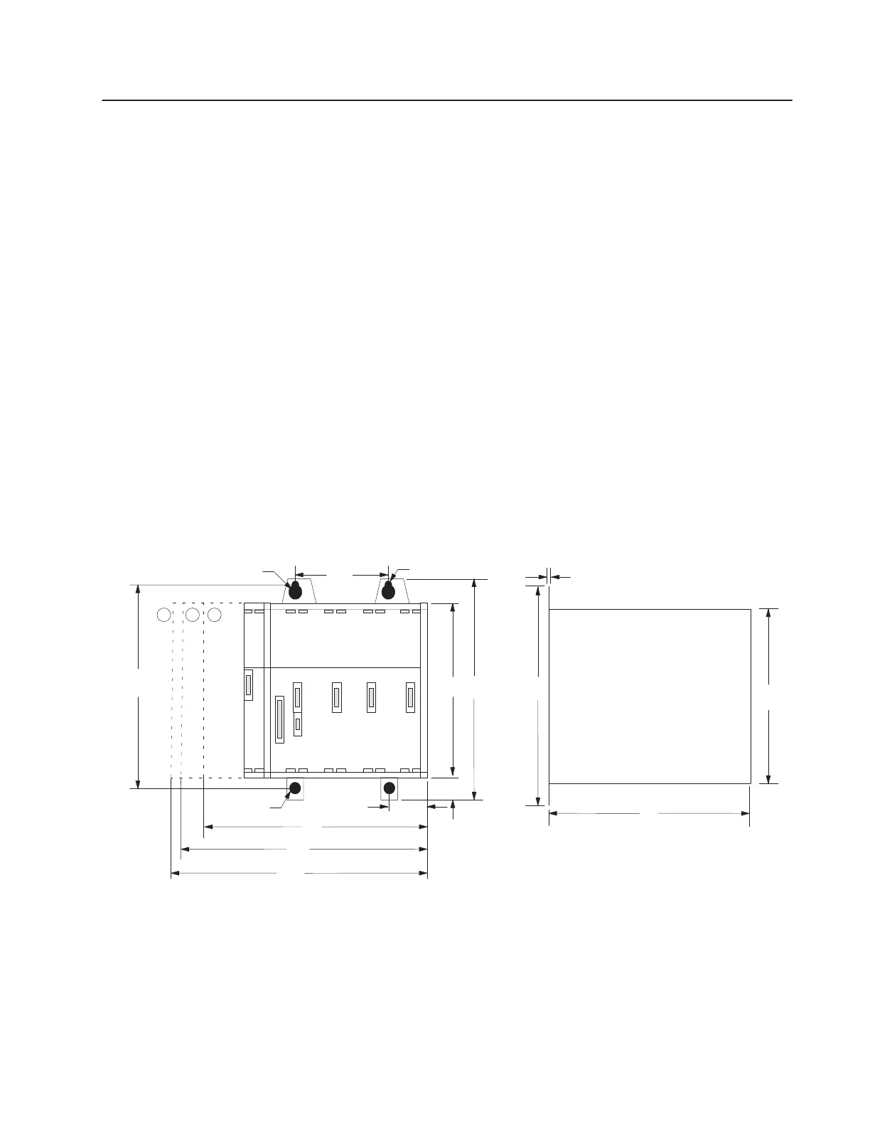
4-Slot Modular Chassis
45
(1.77)
215
(8.46)
235
(9.25)
70
(2.76)
145
(5.71)
Front View
171
(6.73)
140
(5.51)
(6.22)
171
(6.73)
140
158
1
1 Dia.
(0.433)
(5.51)
Left Side View
1.0
(0.04)
5.5 Dia.
(0.217)
5.5 Dia
(0.217)
14
(0.55)
millimeters
(inches)
261
(10.28)
123
➀
Dimensions for power supply catalog number 1746-P1
➁
Dimensions for power supply catalog number 1746-P2 & 1746-P3
➂
Dimensions for power supply catalog number 1746-P4
Mounting Modular
Hardware Style Units

 Loading...


