7–6
Wiring Your I/O Modules
Publication
1747-6.2
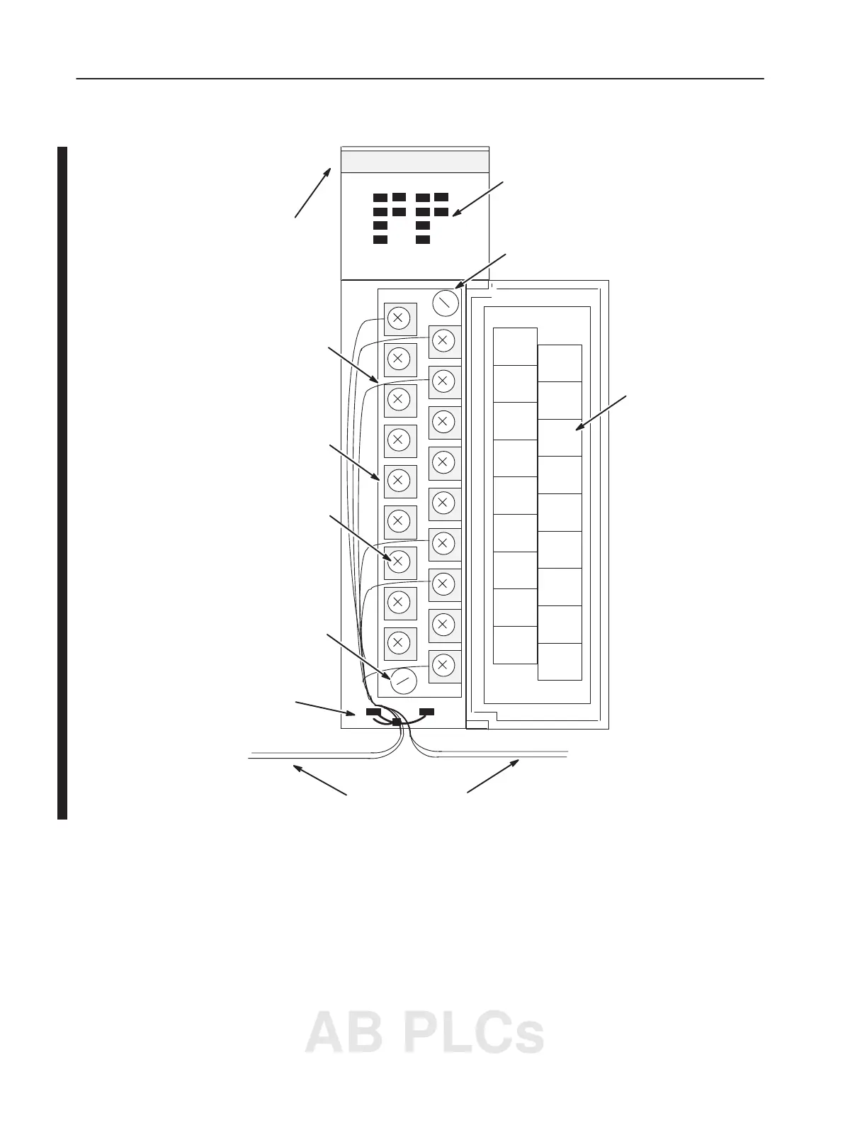
Below is an example of a combination I/O module.
Input and Output Terminals
Connected to Terminal Block
I/O Status Indicators
Terminal Block Screw
max. torque = 0.6 Nm (5.3 in-lbs)
HSCE
OUT
1
OUT 3
OUT 0
OUT 2
Terminal Block (May Be
color-coded and removable on
some modules.)
Hinged Wiring Terminal Door
with Label
OUTPUT INPUT
Tie Wire
OUT
5
NOT
USED
IN 5
OUT 4
IN 0
AC COM
NOT
USED
NOT
USED
NOT
USED
IN 4
IN 3
IN 2
IN 1
1
2
3
4
5
0
1
2
3
4
5
0
VAC–VDC
Wires Leading to Output
and Input Devices
Color Band
Terminal Block Screw
max. torque = 0.6 Nm
(5.3 in-lbs)
Terminal Wiring
max. #14 AWG (2mm
2
)
max. 2 wires per terminal
max torque = 0.9 Nm (8 in-lbs)
Features of an I/O Module
AB PLCs

 Loading...


