C–3Setting Up the DH+ Network
Publication
1747-6.2
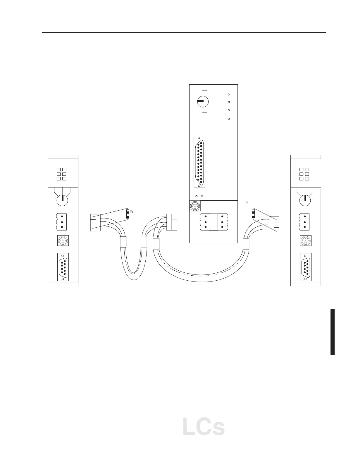
To connect Allen-Bradley devices with other devices over DH+, you
must wire the 3-pin cable connectors so that communication can
occur through the cabling. Each device requires its own node
address.
SLC 5/04 CPU
Connector
PROC
PROG
FORCE
COMM
BATT
RUN
R
E
M
PLC–5/20
PROGRAMMABLE
CONTROLLER
Connector
1
Shield
2
1
Shield
2
Clear
Shield
Blue
AB
Clear
Shield
Blue
SLC 5/04 CPU
1
Shield
2
Connector
Clear
Shield
Blue
Belden
#9463
Belden #9463
RUN PROG
FORCE
RS232
BATT
DH+
FLT
RUN
REM
RUN PROG
FORCE
RS232
BATT
DH+
FLT
RUN
REM
Terminating
Resistor
Terminating
Resistor
Terminate the DH+ link on both ends by connecting a 150Ω, 1/2W
resistor between terminals 1 and 2 of the 3-pin connector when you
are communicating at 57.6K baud with a PLC-5 processor or
115.2K baud with other SLC 5/04 processors. Use an 82Ω, 1/2W
resistor if you are communicating at 230.4K baud with other
SLC 5/04 processors or Series E enhanced PLC-5 processor.
g C
DH
Communication for SLC
5/04 Processors
AB PLCs

 Loading...


