F–5Calculating Heat Dissipation for the SLC 500 Control System
Publication
1747-6.2
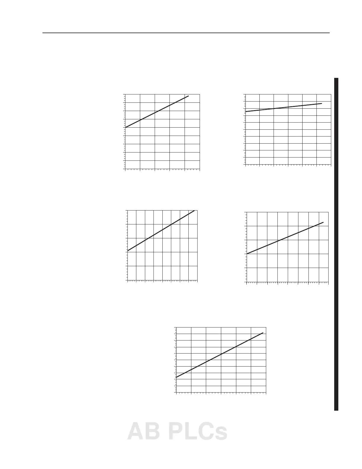
Use the graphs below for determining the power supply dissipation
in step 2 of the worksheet.
0
2
4
6
8
10
12
14
16
18
05
10 15 20 25
Power Supply Dissipation (W
atts)
Power Supply Loading (W
atts)
1746-P1
Power Supply Change in Power
Dissipation due to Output Loading
0
2
4
6
8
10
12
14
16
18
20
0102030405060
Power Supply Dissipation (W
atts)
Power Supply Loading (W
atts)
1746-P2
Power Supply Change in Power
Dissipation due to Output Loading
0
5
10
15
20
25
0 5 10 15 20 25 30 35 40
Power Supply Dissipation (W
atts)
Power Supply Loading (W
atts)
1746-P3
Power Supply Change in Power
Dissipation due to Output Loading
1746-P4
Power Supply Change in Power
Dissipation due to Output Loading
0
5
10
15
20
25
0
10 20 30 40 50 60 70
Power Supply Dissipation (W
atts)
Power Supply Loading (W
atts)
80
0
2
4
6
8
10
12
14
16
18
20
0102030405060
Power Supply Dissipation (W
atts)
Power Supply Loading (W
atts)
1746-P5
Power Supply Change in Power
Dissipation due to Output Loading
Use these Graphs to
Determine the Power
Supply Dissipation
AB PLCs

 Loading...


