5–2
Identifying the Components of Your Processor
Publication
1747-6.2
The SLC 5/01 processor provides:
• two choices of program memory size – 1K or 4K instructions
• control of up to 3840 input and output points
• powerful ladder logic programming instruction set
• subroutines
• a DH-485 communication channel (peer-to-peer communication
response to message commands only)
• capacitor backup for the -L511; battery backup for the -L514
• program using the Hand-Held Terminal (HHT) or programming
software
• UL listed, CSA approved, CE compliant
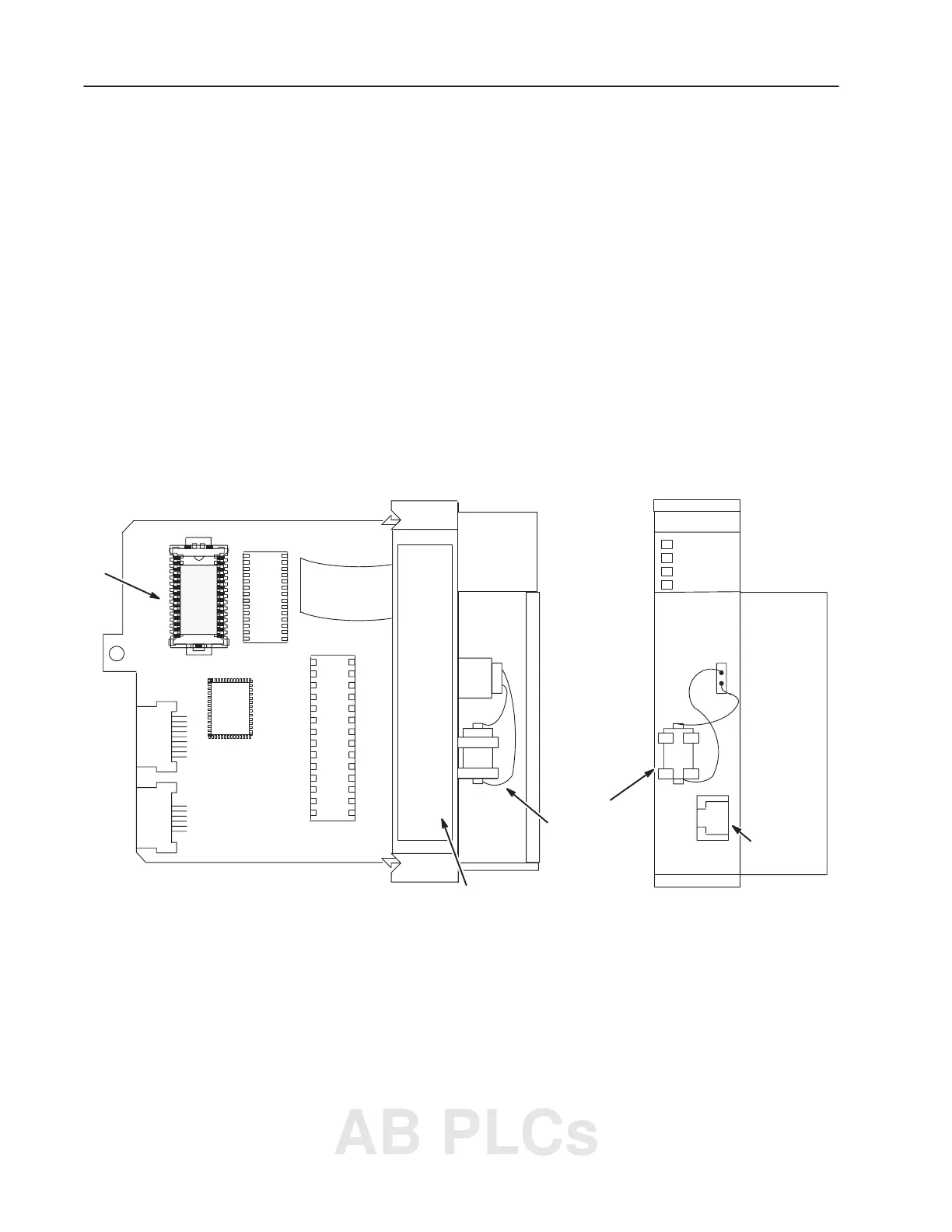
The figure below shows the hardware components of the SLC 5/01
processor (1747-L511 and 1747-L514).
SLC
5/01 CPU
PC RUN
CPU FAULT
FORCED I/O
BATTERY LOW
Left Side View
Front View
Battery
(Provides Back-up
Power for the
CMOS RAM)
Memory Module
and Socket
Location of Serial and
Catalog Numbers
DH-485
Channel 1
SLC 5/01 Processor
Hardware Features
AB PLCs

 Loading...


