5–3
Identifying the Components of Your Processor
Publication
1747-6.2
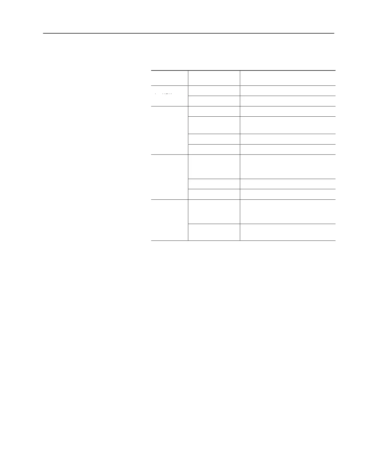
The table below provides a general explanation of the SLC 5/01
processor LEDs.
➀
Processor
LED
When It Is Indicates that
PC RUN
On (steadily) The processor is in the Run mode.
C
(Color: red)
Off
The processor is in a mode other than Run.
Flashing (at power up) The processor has not been configured.
CPU FAULT
Flashing (during
operation)
The processor detects a major error either in
the processor, expansion chassis or memory.
C
r:
red
On (steadily) A fatal error is present (no communication).
Off There are no errors.
FORCED I/O
Flashing
One or more input or output addresses have
been forced to an On or Off state but the
forces have not been enabled.
(Color: red)
On (steadily)
The forces have been enabled.
Off No forces are present or enabled.
BATTERY
LOW
On (steadily)
The battery voltage has fallen below a
threshold level or the battery and the battery
jumper are missing.
LO
(Color: red)
Off
The battery is functional, or the battery
jumper is present.
➀
See
chapter 10 for more information on LED status.

 Loading...


