A–12 Setting Up the DH-485 Network
Publication
1747-6.2
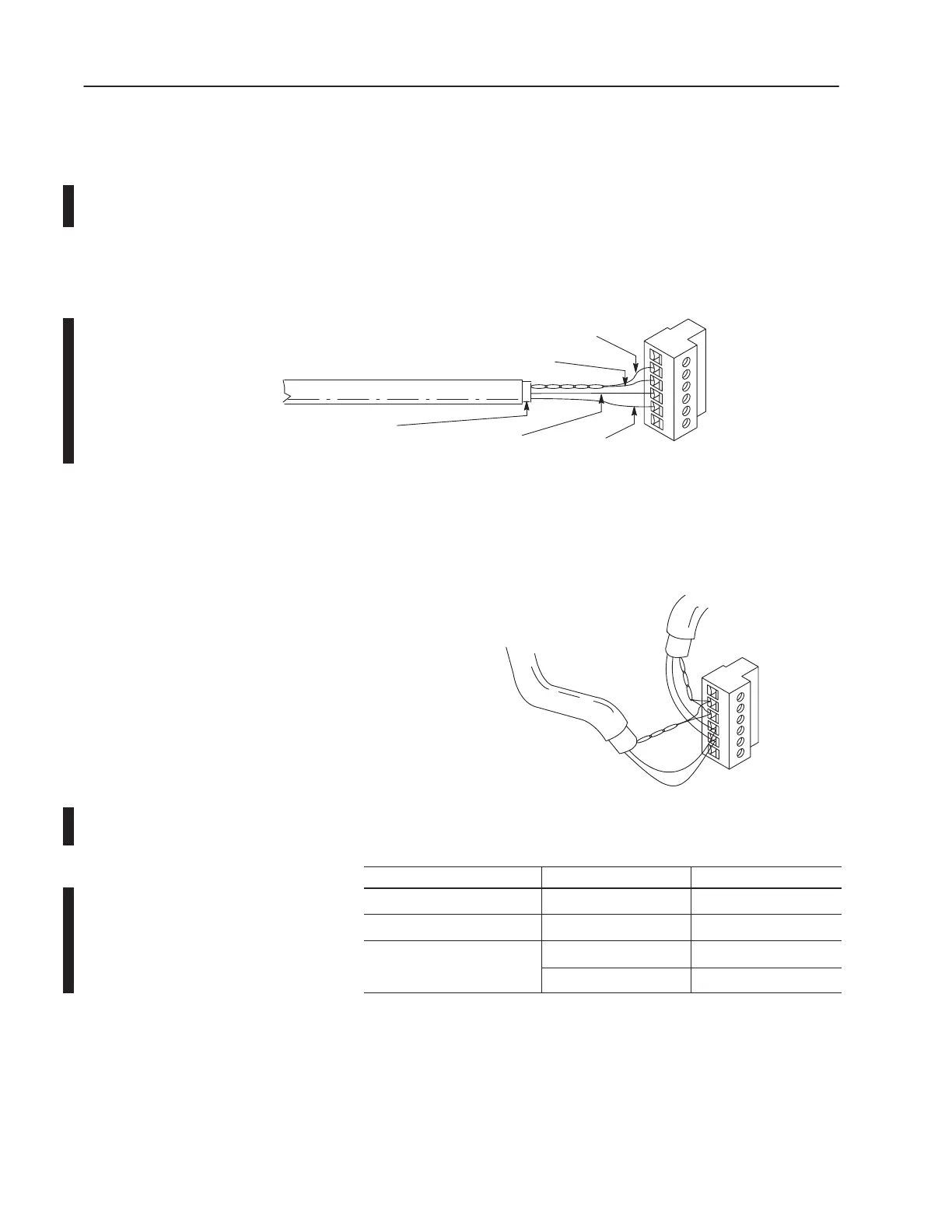
Connecting the Communication Cable to the Isolated Link
Coupler
Attach the terminal block of the link coupler to the Belden #3106A
or #9842 cable as shown below. Additional terminal blocks are
available for replacement, see chapter 11.
Single
Cable Connection
6Termination
5A
4B
3Common
2Shield
1Chassis
Ground
White with Orange Stripes
Orange with White Stripes
Blue (#3106A) or
Blue with White Stripes (9842)
Drain Wire
Shrink T
ubing Recommended
Belden #3106A or #9842
Multiple
Cable Connection
to Successive Device
to Previous Device
19525
The table below shows wire/terminal connections for DH-485
connectors for Belden #3106A.
For this Wire/Pair Connect this Wire To this Terminal
Shield/Drain Non-jacketed Terminal 2 – Shield
Blue Blue Terminal 3 – (Common)
White with Orange Stripe Terminal 4 – (Data B)
h
e/Or
ge
Orange with White Stripe Terminal 5 – (Data A)

 Loading...


