C–2 Setting Up the DH+ Network
Publication
1747-6.2
The SLC 5/04 processors let you operate DH+ communication
protocol by means of the DH+ communication channel 1. The SLC
5/04 processors also support DF1 full-duplex protocol, DF1
half-duplex master and slave protocol, ASCII, or DH-485 via its
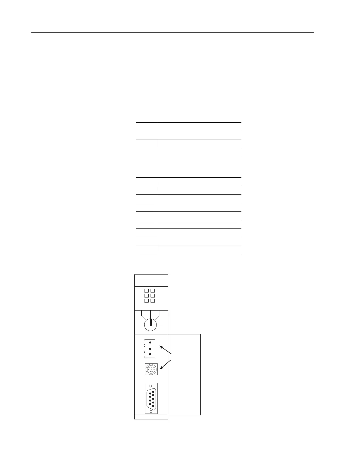
RS-232 port, channel 0. The 3-pin connector, provided with the SLC
5/04 processors, is for actual DH+ communication and the 8-pin
connector is for monitoring DH+ communication.
DH+ Channel 1 3-Pin
Pin Pin Name
1
DH+ Data Line 1
2 Shield
3
DH+ Data Line 2
DH+ Channel 1 8-Pin
Pin Pin Name
1
DH+ Data Line 2
2 No Connection
3 Shield
4
+24V
5 No Connection
6
DH+ Data Line 1
7
+24V Return
8 No Connection
The location of channel 1 is detailed in the drawing below.
Front View
SLC
5/04 CPU
DH+
Channel 1
RUN PROG
FORCE
RS232BATT
DH+FLT
RUN
REM
SLC 5/04
DH+ Communication

 Loading...


